Raptor-C with FALCON Application - Product Manual
siliXcon Raptor-C Motor Controller Firmware Application: FALCON
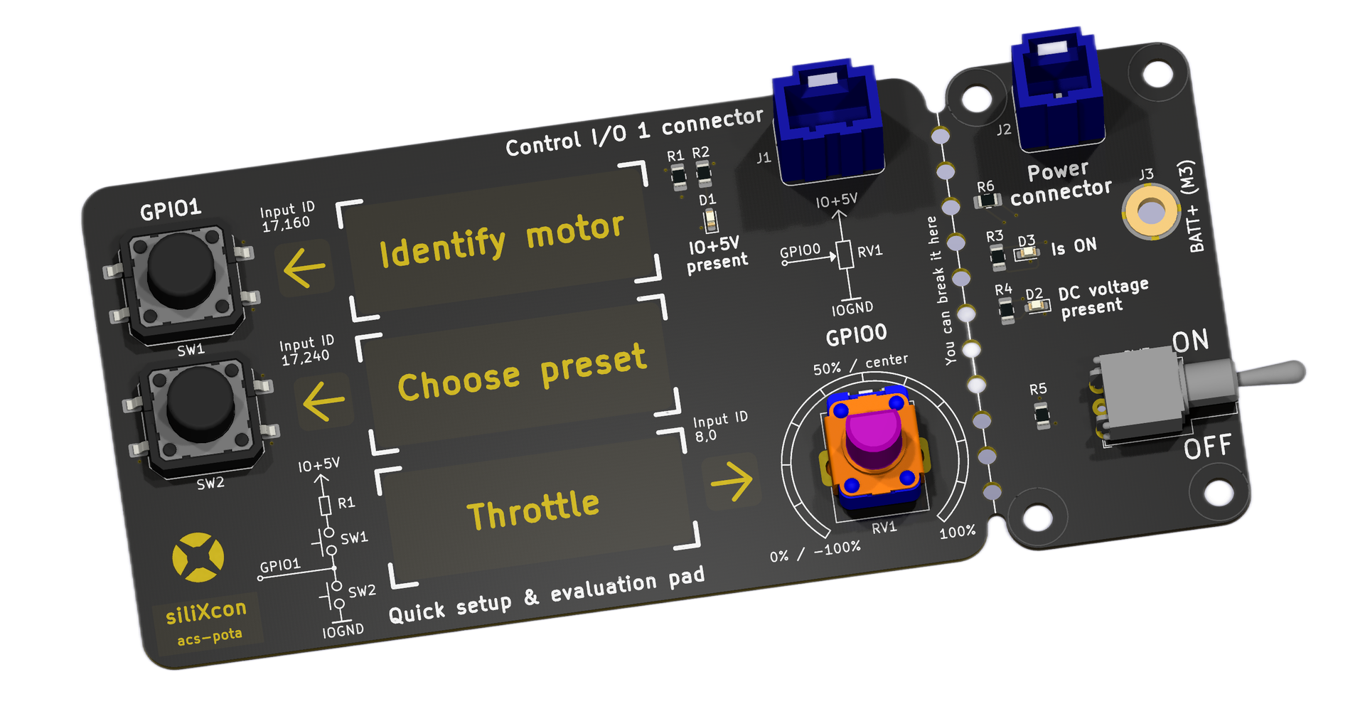
Quick Start with Quick-Setup Pad
Don't want to read the full manual? If you have the Quick-setup pad accessory, you can get the motor running in minutes without installing any software.
What you need
- Raptor-C controller
- Battery (matching the controller's voltage rating)
- BLDC/PMSM motor (matched to controller power rating)
- Quick-setup pad (supplied with your sample)
Hardware preparation
- Connect power leads from the controller to the battery and motor. Ensure the motor power matches the controller specifications. Mount the motor safely on a bench. Do not use a power supply.
- Plug the two JST connectors labeled "Control I/O 1" and "Power" from your controller into the Quick-setup pad.
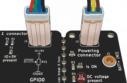
- Verify the "DC voltage present" LED is active on the pad. If not, check battery connection.
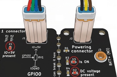
- Turn on the rocker switch. The "Is ON" and "IO+5V present" LEDs should illuminate. The controller's on-board LED should indicate no error.
Motor identification
WARNING: The identification procedure pushes up to half of the controller's rated current through the motor coils. Ensure your motor can handle this thermally.
- Ensure the motor can spin freely.
- Press and hold the A/Identify motor button for 5 seconds until the procedure starts (signaled acoustically).
- Wait for the confirmation melody indicating success.
- The motor parameters are now saved. Repeat this step only when changing to a different motor type.
Choose a function preset (Acoustic menu)
- Press and hold the B/Choose preset button for 5 seconds to enter the acoustic menu.
- While in the menu:
- Press A repeatedly to cycle through current (power) levels: 12.5%, 25%, 37.5%, 50%, 67.5%, 75%, 87.5%, 100%. Each level is signaled with a distinct melody.
- Press B repeatedly to cycle through function presets:
| Beeps | Preset | Description |
|---|---|---|
| 1 | Aircraft | Uni-directional prop control with freewheel (standard BLDC ESC behavior) |
| 2 | RC Car | Combined brake and reverse. Negative = brake; release then negative again = reverse |
| 3 | Torque | Bidirectional symmetrical, mapped to current (torque) |
| 4 | Voltage | Bidirectional symmetrical, mapped to voltage (dynamic/acrobatic) |
| 5 | Speed | Bidirectional symmetrical, mapped to speed closed loop (governor) |
- After 5 seconds of no button presses, the menu exits and saves your choices (confirmation melody).
Try the throttle
- Use the potentiometer on the Quick-setup pad, or connect a servo PWM / analog signal.
- After changing function, the input is disarmed. Move the throttle to the neutral position first to arm.
Restore factory settings
Press and hold both A and B buttons simultaneously for 5 seconds to discard all settings and return to factory defaults.
Table of Contents
- Product Overview
- Physical Characteristics
- Electrical Specification
- Connector Pinout
- Accessories and Mounting
- Connecting to the Controller (SWTools)
- FALCON Application Overview
- State Machine
- Initial Configuration
- Input Configuration
- Control Modes
- Safety Features
- Emergency Stop and Prop Docking
- Function Presets (Quick Setup)
- CAN Communication
- LED Status Indicator
- Troubleshooting
1. Product Overview
The Raptor-C is a compact, high-performance brushless motor controller from the siliXcon SC controller family. It is available in two form factors:
| Raptor-C Fan | Raptor-C Flat |
|---|---|
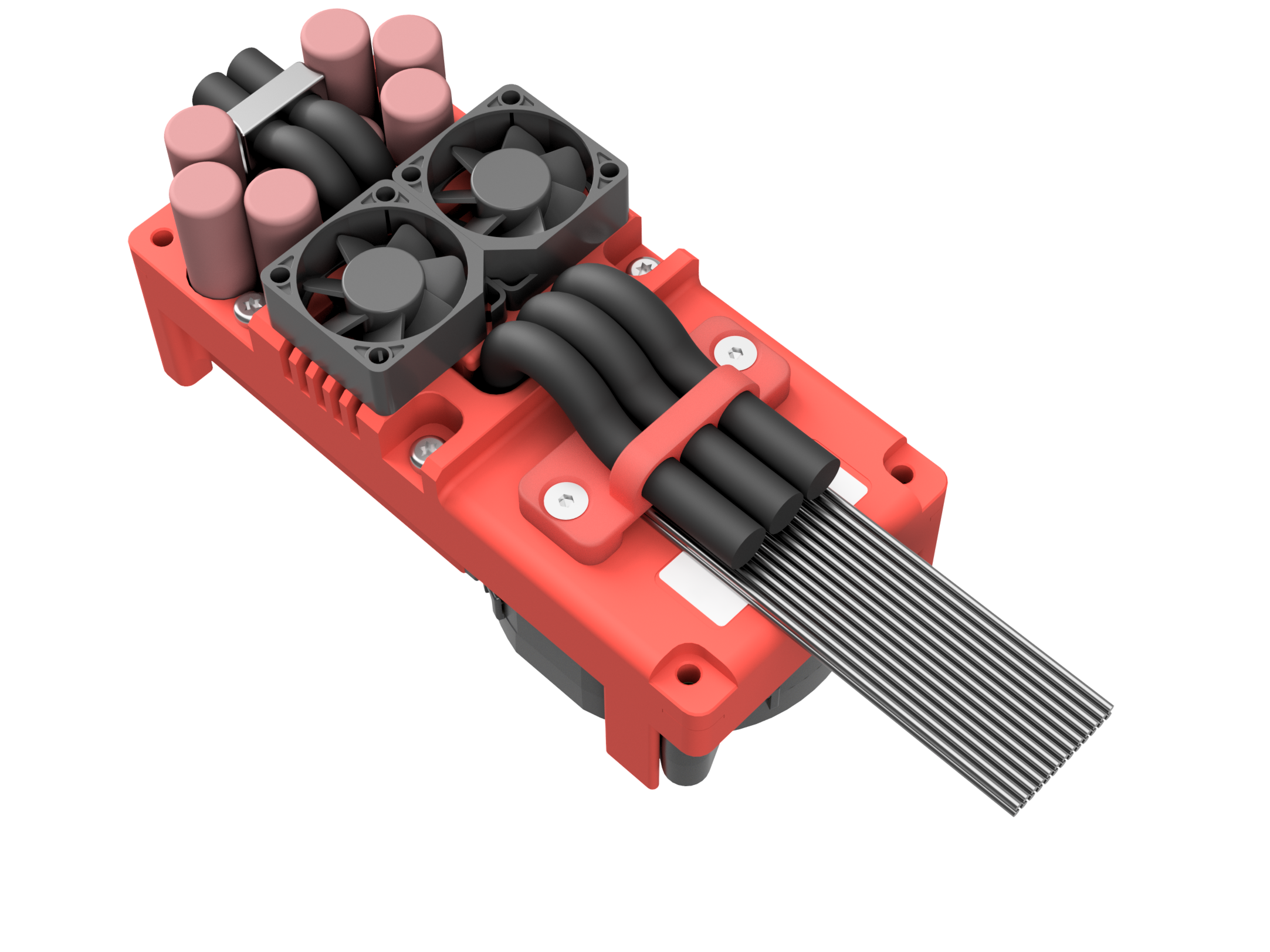 | 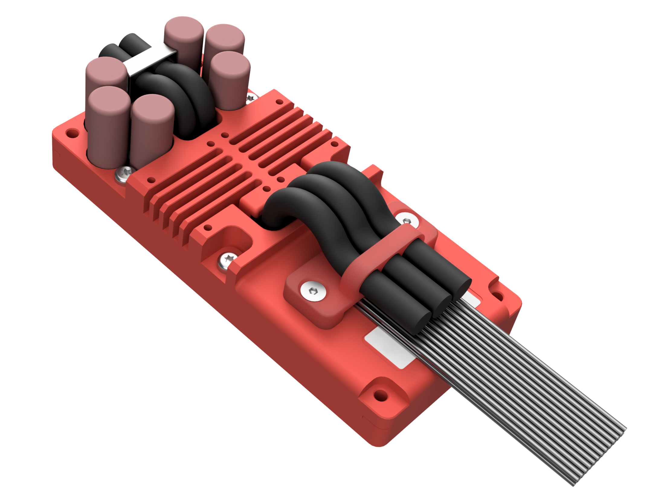 |
| Active fan-cooled (53.0 x 116.6 x 51.4 mm, 440 g) | Compact flat form factor (37.5 x 116.6 x 51.4 mm, 330 g) |
Applications
- Compact multirotor and quadcopter drone propulsion
- Military micro-UAV and small tactical drone drives
- Aerial survey, mapping, and inspection platforms
- Defense perimeter security and surveillance drones
- First-responder and search-and-rescue aerial systems
- Electronic warfare and signal relay UAV powertrains
Part Number: 25xxx1060
The Raptor-C uses the 25xxx1060 product variant (100 V transistors).
2. Physical Characteristics
Raptor-C Fan
- Width: 53.0 mm
- Height: 116.6 mm
- Thickness: 51.4 mm
- Weight: 440 g
Raptor-C Flat
- Width: 37.5 mm
- Height: 116.6 mm
- Thickness: 51.4 mm
- Weight: 330 g
Mechanical Reference
| Position | Name |
|---|---|
| 1 | Motor phase lead wires |
| 2 | Battery + lead wire |
| 3 | Battery - lead wire |
| 4 | Mounting surface |
| 5 | Product label |
| 6 | Status LED |
| 7 | Signal connectors - JST JWPF |
The controller should be installed by placing the mounting surface (4) on a flat metal surface and securing it with four screws. The status LED (6) indicates error states.
3D Models and Drawings
- Raptor-C Fan: Drawing (PDF)
- Raptor-C Flat: Drawing (PDF)
3. Electrical Specification
Input Voltage Rating
| Parameter | Value |
|---|---|
| Transistors | 100 V |
| Maximum working voltage | 84 V |
| Full limitation voltage | 92 V |
| Critical error voltage (max) | 100 V |
| Li-ion battery nominal voltage | 72 V |
| Li-ion series cells count | 20S |
| Minimum working voltage | 18 V |
| Threshold voltage | 16 V |
| Critical error voltage (min) | 12 V |
DC Bus Capacitance
| Voltage variant | Capacitance |
|---|---|
| 10 (100 V) | 1350 uF |
Output Current and Power Rating (VECTOR driver)
| Parameter | Raptor-C Flat | Raptor-C Fan |
|---|---|---|
| Maximum continuous power dissipation | 100 W | 80 W |
| Peak phase current (10 sec) | 280 A (198 Arms) | 280 A (198 Arms) |
| Peak power (10 sec) | 20.4 kW @ 84 V | 20.4 kW @ 84 V |
Note (Fan edition): Continuous ratings assume fan installed, air path not obscured, air temperature 20 deg C.
Fixed Current Limits
| Parameter | Value |
|---|---|
| RMS current limit | 300 Arms |
| Burst current limit | 600 A |
Environmental Specification
| Parameter | Value |
|---|---|
| Operation temperature (no limitation) | -20 deg C .. 60 deg C |
| Operation temperature (with power limitation) | -20 deg C .. 80 deg C |
| Humidity | 5% .. 85% (not tested) |
| Ingress protection | IP40 |
Higher ingress protection rating possible on demand.
4. Connector Pinout
Power Connections
The Raptor-C uses free silicone lead wires (10 mm2) for power:
- Battery+: Red lead wire
- Battery-: Black lead wire
- Motor phase A, B, C: Lead wires
Terminate with connectors appropriate for your application.
Signal Connectors (JST JWPF)
Power Connector (3-pin)

| Pin | Wire Colour | FALCON Function |
|---|---|---|
| 1 | Brown | Internal supply input (KEY) |
| 2 | Yellow | Power on/off control |
| 3 | Black | Power ground |
Control I/O 1 Connector (4-pin)

| Pin | Wire Colour | FALCON Function |
|---|---|---|
| 1 | Black | Signal ground |
| 2 | Blue | Battery temperature sensor 2 (in_btemp2) |
| 3 | Green | Analog throttle input (in_analog) / Battery temperature sensor 1 (in_btemp1) |
| 4 | Red | 5 V supply for sensors |
Control I/O 2 Connector (8-pin)

| Pin | Wire Colour | FALCON Function |
|---|---|---|
| 1 | Orange | 10 V supply for throttle potentiometer |
| 2 | Yellow | PWM throttle input (in_ppm_ch) |
| 3 | Blue | E-stop digital input (in_estop) |
| 4 | Green | Quick-setup pad button (in_quick_setup) |
| 5 | White | 3 V supply |
| 6 | Black | Signal ground |
| 7 | Black | Signal ground |
| 8 | Red | 5 V supply for sensors |
Digital OUT1 Connector (2-pin)

| Pin | Wire Colour | FALCON Function |
|---|---|---|
| 1 | Brown | Contactor/relay drive + |
| 2 | Green | Contactor/relay drive - |
Motor Sensor Connector (8-pin)

| Pin | Wire Colour | FALCON Function |
|---|---|---|
| 1 | Green | Hall sensor V / SIN encoder |
| 2 | Blue | Hall sensor U / COS encoder |
| 3 | Yellow | Hall sensor W / COM |
| 4 | White | Motor temperature sensor (NTC) |
| 5 | Red | 5 V supply for motor sensors |
| 6 | Brown | Encoder B / data |
| 7 | Black | Sensor ground |
| 8 | Violet (Orange) | Encoder A / CLK / Prop dock reference sensor |
CAN Connector (3-pin)

| Pin | Wire Colour | FALCON Function |
|---|---|---|
| 1 | Black | Communication ground |
| 2 | Yellow | CAN bus high (status messages, VCU control) |
| 3 | Green | CAN bus low |
USB Connector (4-pin)

| Pin | Wire Colour | FALCON Function |
|---|---|---|
| 1 | White | USB data + (SWTools connection) |
| 2 | Green | USB data - |
| 3 | Black | USB ground |
| 4 | Red | USB 5 V |
UART COM Connector (4-pin)
| Pin | Wire Colour | FALCON Function |
|---|---|---|
| 1 | Black | Communication ground |
| 2 | White | UART transmit |
| 3 | Blue | UART receive |
| 4 | Red | 5 V supply |
All signal inputs are galvanically isolated from BATT-.
5. Accessories and Mounting
Mating Connectors (Signal)
| Connector | Part Number |
|---|---|
| DOUT | JST 02T-JWPF-VSLE-S |
| DIN | JST 02R-JWPF-VSLE-S |
| Motor sensor | JST 08R-JWPF-VSLE-D |
| Control I/O 2 | JST 08T-JWPF-VSLE-D |
| Control I/O 1, UART | JST 04T-JWPF-VSLE-S |
| Power | JST 03T-JWPF-VSLE-S |
| CAN | JST 03R-JWPF-VSLE-S |
| USB | JST 04R-JWPF-VSLE-S |
Note: Power connections (battery and motor phases) are free silicone lead wires (10 mm2). Terminate them with connectors appropriate for your application.
Crimp Tools
- Receptacle contact 22-26 AWG: SWPR-001T-P025
- Tab contact 22-26 AWG: SWPT-001T-P025
- Crimp tool: WC-JWPF
- Removal tool: EJ-JWPF
Mounting
- 4x M4 or M5 screws (M4 through-hole, M5 threaded in heatsink)
- For through-hole mounting, minimum thread depth is 1.5x screw diameter
- Apply thermal grease to mounting area for improved cooling (e.g. Electrolube HTC or AG termopasty HPX)
Connector Set
siliXcon can provide a complete set of mating connectors for prototyping. Signal JST connectors come pre-crimped with 10 cm cables. Contact siliXcon customer support for details.
6. Connecting to the Controller (SWTools)
What is SWTools?
SWTools is the software package for configuring, monitoring, and managing siliXcon controllers. With SWTools you can:
- Configure parameters
- Observe state variables in real-time
- Execute commands
- Upgrade firmware
- Save/load configuration files
- View real-time data with the built-in scope
Download SWTools from: https://silixcon.com/download-sw-tools/
Recommended Connection: CAN Bus
The recommended interface is CAN using a Kvaser or PeakCAN USB dongle.
Hardware setup:
Wire the CAN dongle to the Raptor-C CAN connector:
- CANH (pin 2, yellow wire)
- CANL (pin 3, green wire)
- COMGND (pin 1, black wire)
Alternative: USB
USB can be used but is not recommended for operation because:
- USB is galvanically connected to BAT-, creating interference and safety risks
- To communicate during operation, connect battery first, then USB
USB is suitable for:
- Downloading logs without power
- Uploading configuration without power
- Quick bench testing
Powering On
- Connect the battery to the AS150 connectors
- Apply power to the POWER pin (pin 2 of the Power connector) depending on your power-on variant:
- Constant on: Controller powers on when battery is connected (KEY resistor installed)
- Flip-flop: Momentary pulse on POWER pin toggles on/off
- Activation input: Continuous high on POWER pin keeps controller on
- The status LED should illuminate indicating the controller is alive
First Connection in SWTools
- Open SWTools
- Select your interface (e.g.
kvaserorpcan) and configure the CAN bitrate (default: 500 kbit/s) - The controller should appear in the device list at its address (default: 0)
- You can now browse the parameter tree, observe states, and configure the application
7. FALCON Application Overview
FALCON is the firmware application running on your Raptor-C. It is designed for RC vehicles, drones, and other remotely controlled vehicles.
Key Features
- Servo PWM and analog throttle inputs with configurable signal conditioning
- Multiple control modes: voltage, current (torque), voltage with freewheel, speed closed loop
- Emergency stop with optional prop docking and position hold
- Quick-setup pad for initial configuration without software
- Function presets for common use cases
- Automatic driver re-initialization after errors
- CAN bus status messages and external VCU control
Enabling FALCON
IMPORTANT: To enable FALCON, set the
configuredparameter to1. Otherwise the controller is disabled at the application level. This prevents accidental activation with an unidentified motor.
In SWTools terminal:
set /configured 1
8. State Machine
The controller always operates in one of the following modes. Lower numbers = higher priority.
The current mode is readable via the /mode state variable.
| Value | Mode | Description |
|---|---|---|
| 0 | MODE_STOP | Driver or common block error. Check /driver/error and /common/error. |
| 10 | MODE_NOCONFIG | configured is 0 or -1. Set to 1 to proceed. |
| 90 | MODE_INVALID_SIGNAL | Input signal is out of range or invalid (sig_throttle is NaN). |
| 94 | MODE_FREEWHEEL | Freewheel engaged via CAN control message (control_mode = 0). |
| 95 | MODE_ESTOP | Emergency stop is activated. |
| 96 | MODE_DOCKING | Prop docking in progress. |
| 97 | MODE_DOCKED | Prop is docked and held. |
| 100 | MODE_IDLE | Throttle command is at zero. |
| 110 | MODE_ACC | Accelerating (positive throttle). |
| 115 | MODE_REVERSE | Reversing (negative throttle). |
| 120 | MODE_BRAKE | Braking (combined brake/reverse mode). |
| 200 | MODE_OVERRIDEN | Driver overridden via Driver API or run command. |
9. Initial Configuration
Step 1: Connect and Power On
See Section 6.
Step 2: Verify Firmware
Check that the SWID contains FALCON. In the SWTools terminal:
get /common/swid
Step 3: Configure the Motor Driver
Before enabling FALCON, configure the low-level motor driver. At minimum:
- Set motor pole pairs
- Run motor identification (auto-detection of motor parameters)
Refer to the driver documentation for your motor type.
Step 4: Enable FALCON
set /configured 1
Step 5: Verify Input Signal
Check that your throttle input is recognized:
get /io/sig_throttle
The value should respond to your throttle input with values between -1 and 1.
Step 6: Save Configuration
save
This persists all parameters to non-volatile memory.
10. Input Configuration
FALCON supports two throttle input sources. PWM takes priority when both are valid.
Input Sources
| Parameter | Path | Description |
|---|---|---|
in_ppm_ch | /io/in_ppm_ch | Servo PWM input channel. Set to -1 to disable. |
in_analog | /io/in_analog | GPIO ID for analog input. Set to 0 to disable. |
in_estop | /io/in_estop | GDIN/DIN ID for E-stop input. Set to 0 to disable. |
in_quick_setup | /io/in_quick_setup | GDIN ID for Quick-setup pad button. Set to 0 to disable. |
in_btemp1 | /io/in_btemp1 | GPIO ID for battery temperature sensor 1. Set to 0 to disable. |
in_btemp2 | /io/in_btemp2 | GPIO ID for battery temperature sensor 2. Set to 0 to disable. |
Signal Conditioning Chain
/pwm_input/- Converts captured pulse width (us) into normalized sig_pwm with timeout-based loss-of-signal detection/analog_input/- Converts raw mV from GPIO into normalized sig_analog with out-of-range detection/csc/- Applies deadzone, hysteresis, and low-pass filtering on the selected signal
If both inputs are valid, PWM has priority. If PWM becomes invalid, analog is used as fallback.
Typical Wiring (Servo PWM)
Connect your RC receiver servo output to the default PWM input pin:
- Signal wire to the appropriate GPIO pin (check
in_ppm_chdefault for your hardware) - Power from IO+5V (red) on Control I/O 1
- Ground to IOGND (black) on Control I/O 1
11. Control Modes
Forward Drive Mode (/ctl_mode)
| Value | Name | Description |
|---|---|---|
| 1 | VLT | Voltage mode |
| 2 | CUR | Current (torque) mode |
| 3 | VLTFW | Voltage with freewheel mode |
Reverse Mode (/ctl_reverse_mode)
| Value | Name | Description |
|---|---|---|
| -1 | Use ctl_mode | Same as forward mode |
| 1 | VLT | Voltage mode |
| 2 | CUR | Current (torque) mode |
| 3 | VLTFW | Voltage with freewheel mode |
Brake Mode (/ctl_brake_mode)
Used when combined brake and reverse is active. Set the driver command mode for braking.
12. Safety Features
safetyopts (bitwise parameter)
| Bit | Name | Description |
|---|---|---|
| 0 | Startup disarm | After startup, throttle is ignored until signal is valid and at zero. Then the system arms. |
| 1 | Runtime disarm | On invalid signal or error, the system disarms. Throttle must return to zero to re-arm. |
drvopts (bitwise parameter)
| Bit | Name | Description |
|---|---|---|
| 0 | Combined brake and reverse | Enables RC car-style combined brake/reverse logic. |
| 1 | Invalid signal E-stop | Triggers E-stop when input signal becomes invalid (NaN). |
| 2 | Zero signal E-stop | Triggers E-stop when input signal is zero. |
13. Emergency Stop and Prop Docking
E-stop can be triggered by: invalid input signal, zero input signal, or dedicated digital input.
Ramp-down Stage
| Parameter | Path | Description |
|---|---|---|
ramp | /estop/ramp | Brake ramp exponent (0-1). Higher = faster braking. |
max_cmd | /estop/max_cmd | Maximum brake command during ramp-down (0-1). |
voltage_thr | /estop/voltage_thr | Motor voltage threshold (%) to transition to hold stage. Set to 0 to disable hold. |
Hold Stage
Once motor voltage drops below voltage_thr:
- Short circuit brake (if
hold_max_cmd= 0): Motor is short-circuited passively. - Active position hold (if
hold_max_cmd> 0): Voltage-based position controller engaged. - Prop docking: If a reference sensor is connected, rotor moves to absolute reference position before holding.
| Parameter | Path | Description |
|---|---|---|
hold_max_cmd | /estop/hold_max_cmd | Max voltage for position hold. 0 = short circuit brake. |
hold_gain | /estop/hold_gain | Position hold controller gain. |
Prop Docking Sensor
For the SC controller family (Raptor-C), the reference sensor connects to the ENCA/CLK pin on the motor sensor connector (pin 8).
14. Function Presets (Quick Setup)
These presets configure FALCON for common use cases. They are also available via the Quick-setup pad acoustic menu.
Preset 1: Aircraft (Default)
Uni-directional prop control with freewheel. Standard BLDC ESC behavior.
- Use default settings as-is.
Preset 2: RC Car with Braking
RC car with combined brake and reverse. Negative input = brake. Release then re-apply negative = reverse.
- Set
drvoptsbits 0 and 1 (value = 3) - Set
/pwm_input/centerto 1500 and/or/analog_input/centerto 2500 - Set
ctl_modeto 2 (current mode) - Set
ctl_reverse_modeto 3 (voltage with freewheel)
Preset 3: Bidirectional Current (Torque) Mode
Symmetrical bidirectional control mapped to current.
- Set
/pwm_input/centerto 1500 and/or/analog_input/centerto 2500 - Set
ctl_modeto 2
Preset 4: Bidirectional Voltage Mode
Symmetrical bidirectional control mapped to voltage. Good for dynamic testing.
- Set
/pwm_input/centerto 1500 and/or/analog_input/centerto 2500 - Set
ctl_modeto 1
Preset 5: Bidirectional Speed Closed Loop
Symmetrical bidirectional with speed governor.
- Set
/pwm_input/centerto 1500 and/or/analog_input/centerto 2500 - Set
ctl_modeto 17 (voltage + speed loop)
15. CAN Communication
FALCON broadcasts periodic status messages and accepts external control commands over CAN bus.
Status Messages
The primary status message is broadcast at CAN ID 0x600 + controller address and contains:
- Current mode
- Throttle signal value
- Motor speed
- Error flags
External VCU Control
An external Vehicle Control Unit can command the controller via CAN ID 0x5F0 + controller address, enabling:
- Throttle override
- Freewheel command
- E-stop trigger
Refer to the full CAN message documentation for byte-level layouts.
16. LED Status Indicator
The status LED on the Raptor-C indicates the controller's operational state:
- Solid on: Normal operation
- Blinking patterns: Various error states
Refer to the LED status table in the full hardware documentation for detailed blink codes.
17. Troubleshooting
| Symptom | Likely Cause | Solution |
|---|---|---|
| Controller does not power on | No power on POWER pin | Check power connector wiring and power-on variant |
| Mode = 0 (MODE_STOP) | Driver error | Check /driver/error and /common/error states |
| Mode = 10 (MODE_NOCONFIG) | FALCON not enabled | Set /configured to 1 |
| Mode = 90 (MODE_INVALID_SIGNAL) | No valid throttle input | Check input wiring, verify sig_pwm or sig_analog responds |
| Motor does not spin | Safety disarm active | Ensure throttle is at zero first, then arm; check safetyopts |
| SWTools cannot find device | Interface issue | Verify CAN wiring (CANH/CANL not swapped), check bitrate, check address |
| USB communication unstable | EMI from motor phases | Use CAN interface instead; USB is not recommended during operation |
Document Information
- Hardware: siliXcon Raptor-C (SC family, 25xxx1060)
- Firmware: FALCON application
- Generated from: siliXcon documentation portal
For the latest information, visit the online documentation or contact siliXcon customer support.