What is the controller?
Functional perspective
Controller for electric propulsion
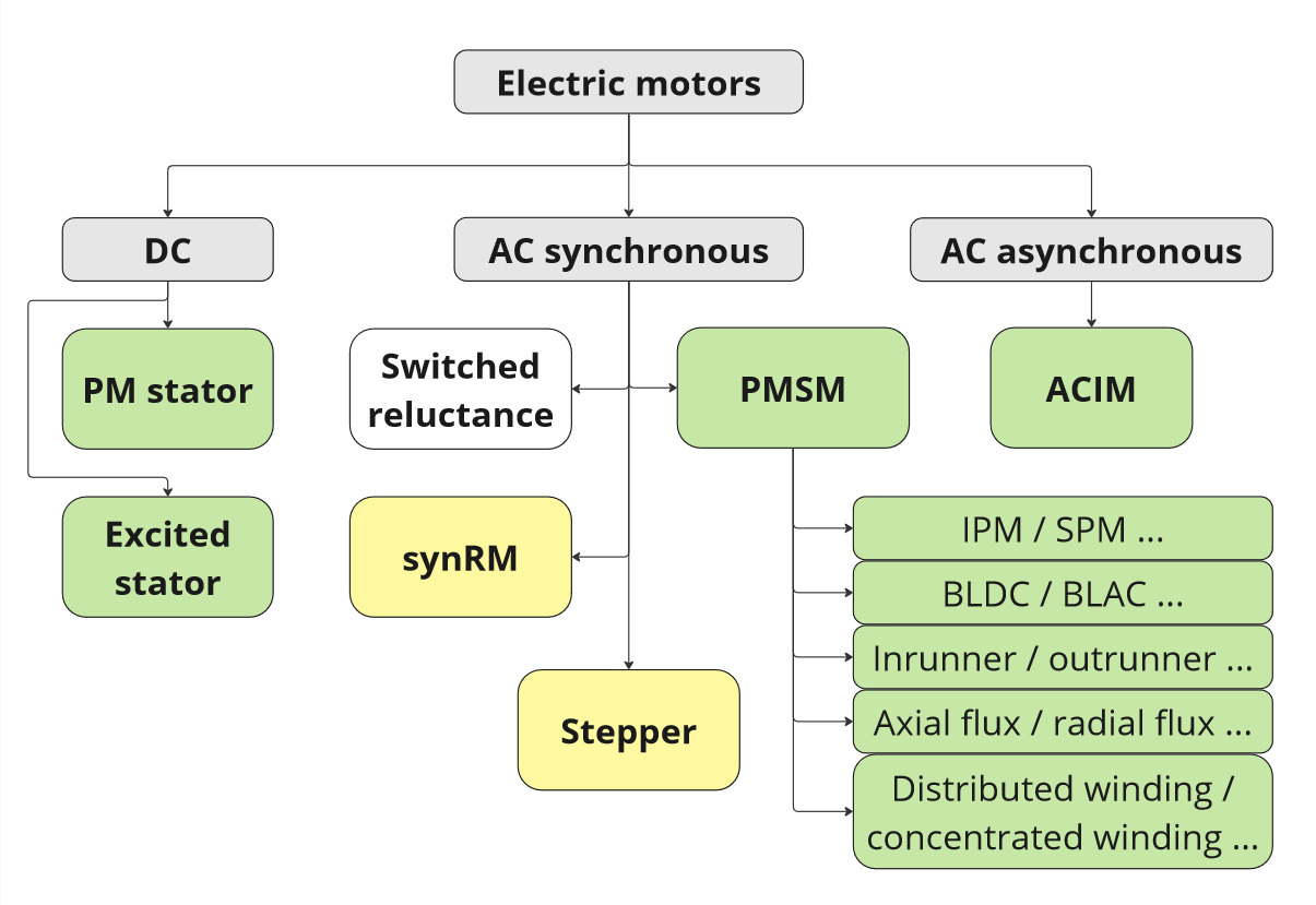
Electric propulsion remains at the heart of our controller's DNA. We've engineered a unified, robust core capable of powering virtually any mobile application for air, land, or water. Physics is our only limit. Motor agnostic by design, the platform seamlessly adapts to your specific powertrain requirements-whether asynchronous or synchronous, reluctance or permanent magnet, low or high inductance, axial or radial flux, inrunner or outrunner, IPM or SPM, high-speed or high-torque configurations. This flexibility delivers precise, efficient control across the entire spectrum of motor technologies, supporting up to 800A and 150V. One platform architecture-unlimited propulsion possibilities.
Controller as a generator
We often get a question: "Do you support regenerative braking?" The answer is: "Of course!" Bidirectional energy flow is fundamental to our platform architecture. We've engineered full four-quadrant operation with seamless transitions between motoring and generating modes. The system delivers precise control across all regenerative scenarios, such as proportional load torque modulation depending on the shaft angle, as well as DC bus current management for optimal battery charging. This symmetrical design enables sophisticated applications from regenerative braking to full starter-generator integration. Deploy confidently in series hybrid, parallel hybrid, or complex multi-controller configurations with inherent ICE coordination and distributed electronic transmission control.
Controller as a servo drive
While the controllers were engineered primarily for power traction applications, their versatile control architecture unlocks exceptional motion control potential. The platform delivers comprehensive servo functionality-including speed, torque, and position control modes-enabling everything from synchronized multi-motor coordination in vehicle systems to precision robotic manipulation. Advanced features such as virtual axis coupling, electronic line shafting, and multi-controller synchronization are native to the architecture. This positions our solution uniquely in the market: servo-grade precision combined with robust high-power electronics and superior dynamic response. The result is a single platform that bridges the gap between heavy-duty traction and fine-resolution motion control.
Controller as a VCU
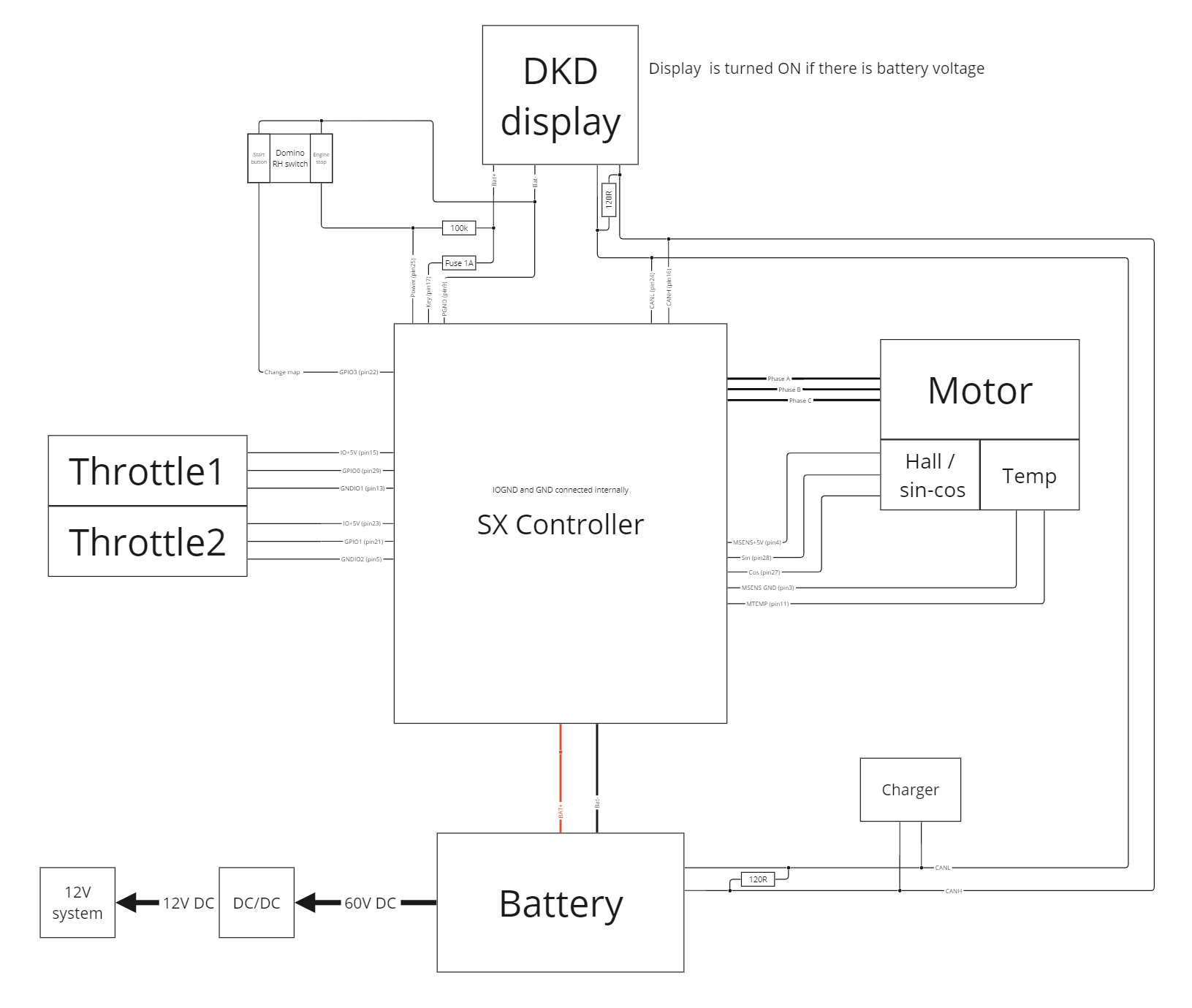
Although the motor control is the foundation, the controller includes plenty of spare computing power, interfacing options, as well as inputs and outputs to ensure its functionality. We offer a great depth of customization on the application layer. User inputs can be processed and evaluated directly by the controller, followed by the execution of the desired actions. The vehicle / axle control can be seamlessly distributed and motion-synchronized across multiple units in a single vehicle. Traction control, combination of servo drive and slip limitations are all native for us. For a simplest example, the figure below shows a system where the controller is the central VCU unit, and the peripheries are connected.
Electronic perspective
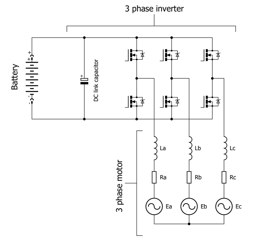
The siliXcon motor controller is an electronic device responsible for controlling electric motors. It operates as a 3-phase inverter that converts the direct current (DC) voltage from the battery into the alternating current (AC) voltage required by a 3-phase motor. The simplified schematic shown in the figure below illustrates this process. The voltage conversion is achieved by switching transistors in the power stage of the controller and connecting the motor's inductances to the positive or negative pole of the battery. The switching of power transistors is modulated to generate a sinusoidal current (or any other desired waveform) in the motor's inductance.
It is important to note that only the currents flowing through the inductances exhibit a sinusoidal waveform. In contrast, the voltages connected to the inductances take the shape of high-frequency square pulses.
Energy perspective
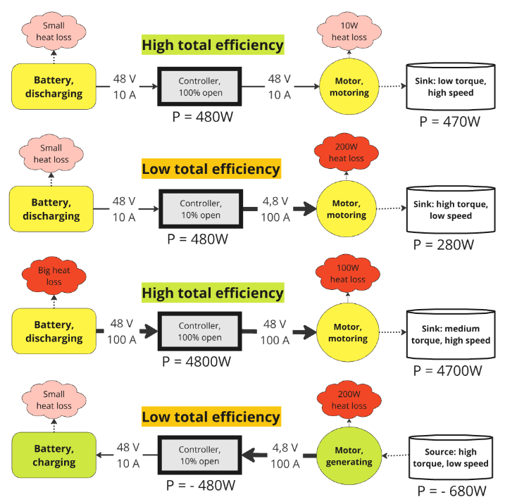
From an energy perspective, the controller functions as both an energy transformer and regulator. It converts the electrical energy from the battery, which consists of direct current (DC) voltage and current, into electrical energy suitable for the 3-phase motor, involving alternating currents (AC) and voltages. Furthermore, the controller manages the direction of energy flow, whether it is from the battery to the motor or vice versa. It is worth noting that the controller exhibits exceptional energy efficiency, reaching up to 98%, and possesses minimal energy storage capacity. As a result, we can usually neglect its losses and conclude that the input power is approximately equal to the output power. However, the currents and voltages on the input and output may vary. The AC output voltage is always lower than or equal to the DC input voltage, whereas the output current is always higher than or equal to the input current (disregarding the AC/DC measurement domains: RMS, amplitude, etc.).
From this perspective of the controller as a near-lossless power gate (a device that can transfer energy between the motor and battery in both directions), the following picture illustrates typical scenarios of the drivetrain in both motoring and generating modes. Please note that the total efficiency is usually dependent on the duty cycle (opening) of the controller. It's important to emphasize that this example illustrates the simplest possible scenario and only considers ohmic losses in the system:
Safety perspective
The aforementioned core principles lead to some implicit safety considerations:
Energy is accumulated in the motor through two different mechanisms. The first mechanism is the current flowing through the motor's inductance, and the second is the rotating mass of the rotor. The battery is the only safe storage space for this energy. When the battery is unplugged, there is no safe place to store the energy. The controller attempts to retain this energy within its DC link capacitor. However, the capacitor does not have sufficient capacity, resulting in a significant increase in voltage, which can lead to overvoltage and potential damage to the controller.
To power the motor controller - this point shares similarities with the previous one. Laboratory power supplies are generally not intended for energy absorption; they can only provide power. When the controller is instructed to brake the motor, it attempts to store energy in the laboratory power supply, which lacks the capability to absorb it. Consequently, this results in overvoltage and typically leads to damage to the controller and/or the power supply. This applies to all commonly used power supply types, not just laboratory power supplies.