II. Basic Configuration
The goal of this page is to configure the BMS to allow operation.
The most basic diagnostic of the BMS is through the BMS state. The state variable is located at /driver/state. Later in this guide, it will be referred to as state. More about state.
Minimum Configuration
Without this configuration, the BMS will not allow operation.
With default parameters, the BMS stays in state INIT.
Pack S Count
Set the number of series cells in the battery pack to parameter /driver/balancing/s_count.
If s_count does not match the actual number of series cells in the battery pack, the BMS will not allow operation.
Temperature Sensor Configuration
The BMS requires at least one temperature sensor connected. The temperature sensor must be a 10k NTC type.
With default parameters, the TS1 and TS2 temperature inputs are configured for 10k NTC. The only thing to configure is the B constant of the NTC. Set these parameters to your NTC sensor B constant:
/driver/temp/ts1Conf/Bconst/driver/temp/ts2Conf/Bconst
Validate the Minimum Configuration
- Make sure the BMS is connected to the battery pack as described in the previous section
- Save the parameters
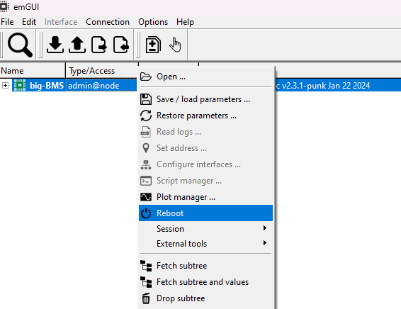
- Reboot
After the reboot, check these values:
/driver/stateshould beIDLE/driver/balancing/cellVoltages— you should read the voltages of the cells in the battery pack/driver/temp/ts1and/driver/temp/ts2— should show the temperature of the connected sensors/driver/voltage— should show the voltage of the battery pack/driver/currentf— current of the battery pack should be under 0.1 A
Other Configuration
BMS Accessory
Using parameter /dispmode, configure the BMS accessory. See Display and LEDs for details.
- It is necessary to reboot the BMS after changing this parameter.
- If you do not have any accessory connected, set parameter
ctlmodeto192. This enables headless mode (BMS ports will be automatically turned on). See Control Mode.
BEST
Battery SOC estimator. Set the parameter /driver/best/P to the number of cells in parallel. Other default settings work for most Li-ion cells.
More about BEST.
After you configure BEST, call the breset command or restart the BMS. The BEST will then restart the estimation.
Undervoltage and Overvoltage Thresholds
These thresholds are set with parameters /driver/balancing/limiter/cellMinVoltage and /driver/balancing/limiter/cellMaxVoltage. The default values work for Li-ion cells.
Short-Circuit Protection
The short-circuit protection is set by parameter /driver/ishrt. Always set the short-circuit protection higher than the ipeak parameter in the controller.
Precharge Current
On BMS1 you can change the precharge current value with parameter /driver/iprch.
Synchronize RTC Time
The BMS1 has a built-in RTC clock. The RTC uses the battery pack as backup power. If you disconnect the pack, you need to synchronize the RTC time again.
The BMS3 does not have an RTC clock. You can synchronize the time too, but the time will drift.
To synchronize the time, use the sync_time.cmd command. This command is distributed with the SWTools.