Electric Motorcycle Implementation
Complete configuration guide for a motorcycle using siliXcon SC controller with LYNX application.
Key Features:
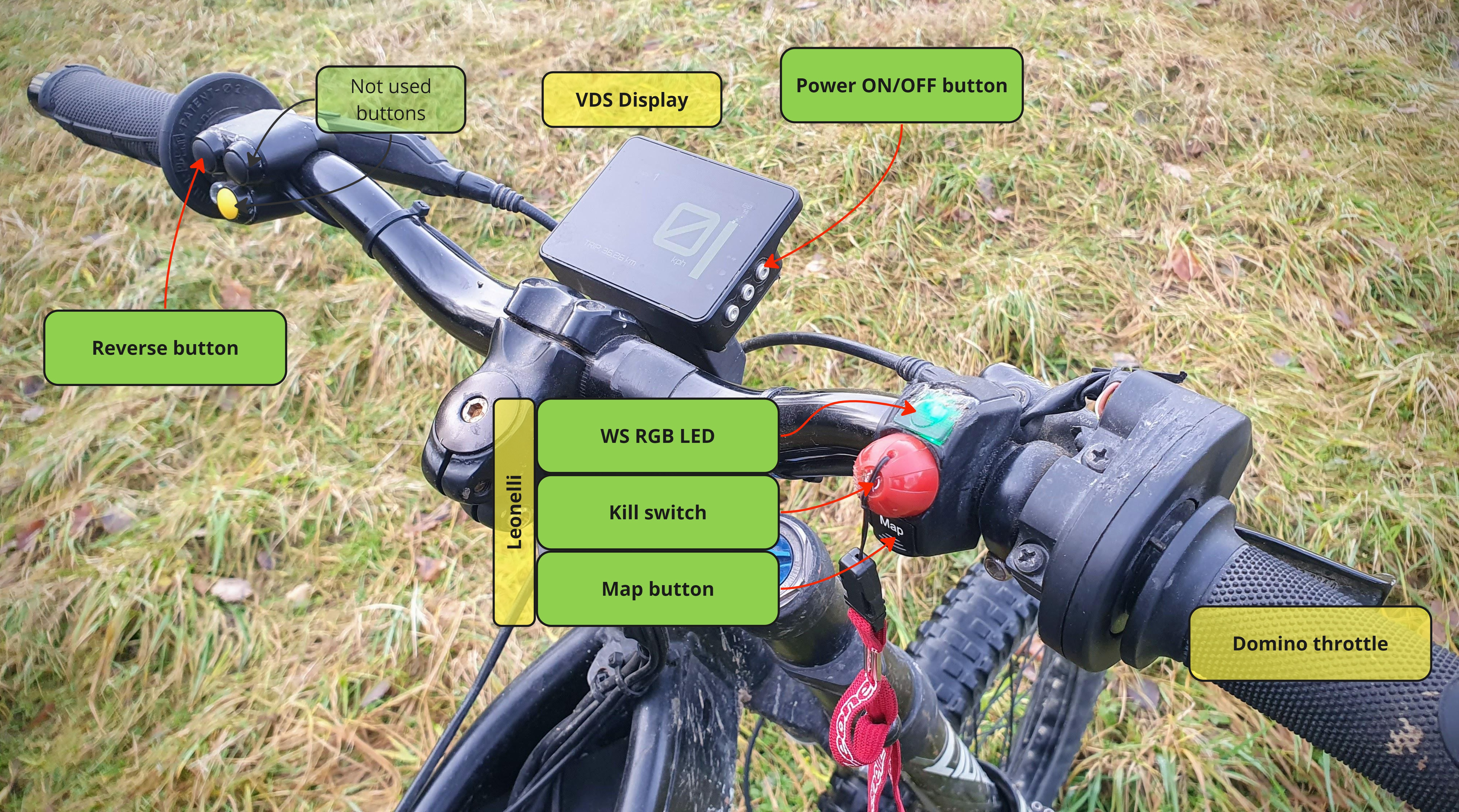
- Standard SC controller with VDS display
- Redundant safety accelerator
- Sensorless motor control
- RGB WS LED map indicator
- Integrated BEST (Battery Estimator) SOC monitoring
System Wiring
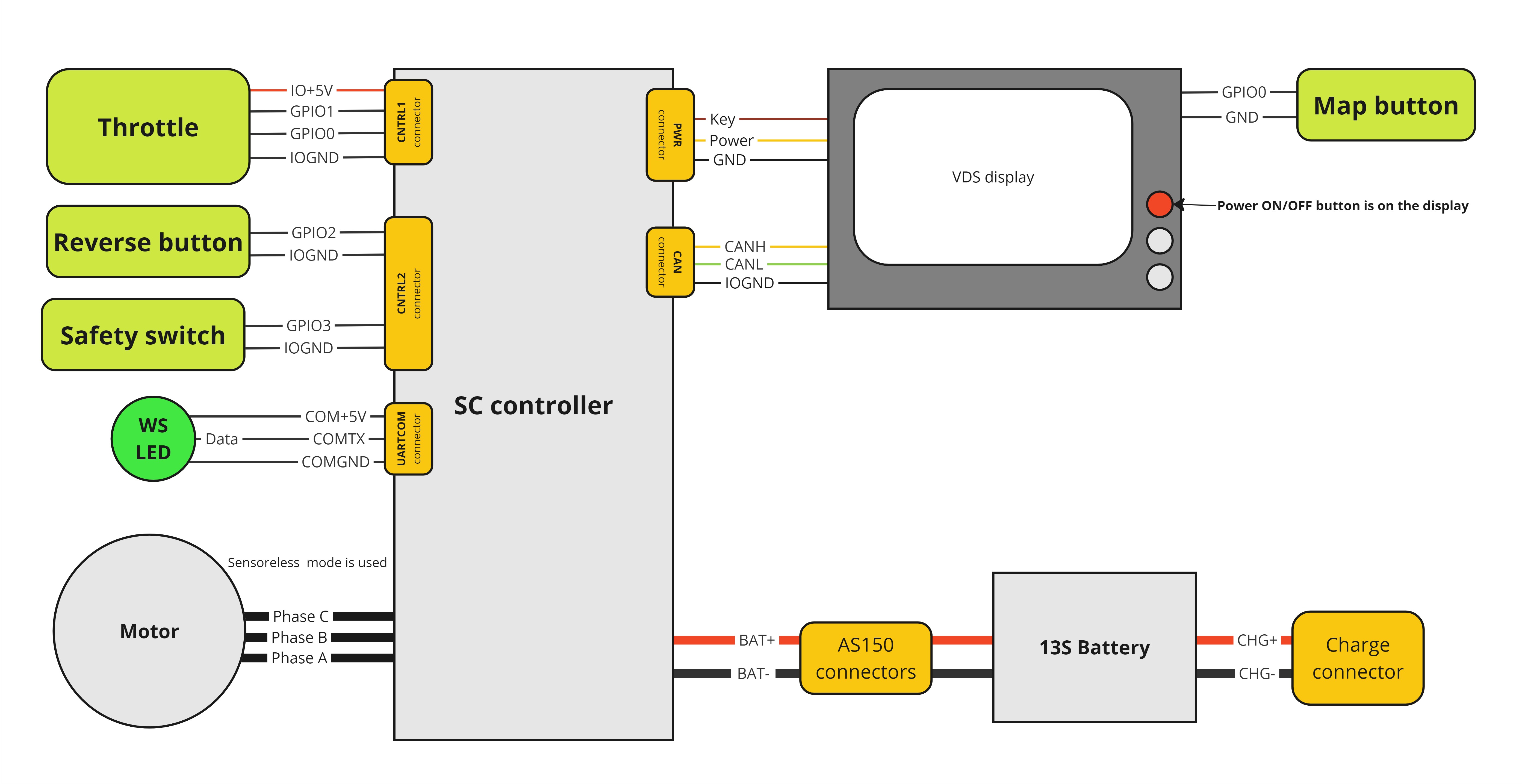
System Configuration
Motor Drive Parameters
Phase current settings determined through thermal testing:
"/driver/iref" : "290.0"  # Reference phase current [A]
"/driver/ipeak" : "320.0" # '[A] peak phase current (negative to switch direction)'
Set the rotor position estimator to sensorless. More info
"/driver/prest" : "1" # 'preferred rotor position estimation mode'
To get the correct motor speed reading, it is necessary to set motor pole pairs count. Also, the rdec value was lovered from default. More info
"/driver/motor/pp" : "8" # '[pairs] pole pair count'
"/driver/limiter/rdec" : "200.0" # '[RPM] speed limiter decrement rate'
Motor settings
All these parameters were automatically identified using the motor identification feature.
"/driver/motor/psi" : "0.007815" # '[Wb] PM flux linkage <0:ACIM> <eps:synRM>'
"/driver/motor/Rt" : "0.007295" # '[Ohm] resistance'
"/driver/motor/Ld" : "1.58330e-5" # '[Henry] D inductance'
"/driver/motor/Lq" : "2.12015e-5" # '[Henry] Q inductance'
"/driver/motor/Da" : "0.004380" # '[1/Amp] aligned inductance derating'
"/driver/motor/Dc" : "0.001217" # '[1/Amp] cross inductance derating'
Battery current and voltage limitation
The battery current and voltage limits are set to protect the battery.
Response time for these currents are dozens of milliseconds. This means, that the battery current can be up to ipeak for a short time.
The voltage reading precision is +-1V, typically +-0.5V.
- Short circuit protection should exceed
ipeak - Overcurrent protection should exceed
ibpos/ibneg - Set overvoltage protection 1V above
ubmax
"/driver/limiter/ibpos" : "180.0" # '[A] battery positive current limit <0:disable>'
"/driver/limiter/ibneg" : "-30.0" # '[A] battery negative current limit <0:disable>'
"/driver/limiter/ubmax" : "54.8" # '[V] battery maximum voltage limit <0:disable>'
"/driver/limiter/ubmin" : "40.0" # '[V] battery minimum voltage limit <0:disable>'
Input configuration
GPIO0 and GPIO1 are used for accelerator input. Set the inputs as "floating" in common IO block. GPIO0 is mapped by default to the accelerator input, only GPIO1 needs to be mapped manually. Both GPIO2 and GPIO3 are set up in "pull-up" configuration.
IN_reverse value is 18 because the input is digital. i.e. GDIN value 18 is used and not GPIO value 10.
The same is true for IN_seatswitch GDIN value 19.
"/io/IN_acc_2" : "9,0" # 'For dual accelerator, GPIO OR DIN ID'
"/io/IN_reverse" : "18,0" # 'DIN ID'
"/io/IN_seatswitch" : "19,0" # 'DIN ID'
"/common/ioconf0" : "0" # '<0:floating> <1:pull-up> <2:pull-down>'
"/common/ioconf1" : "0" # '<0:floating> <1:pull-up> <2:pull-down>'
"/common/ioconf2" : "1" # '<0:floating> <1:pull-up> <2:pull-down>'
"/common/ioconf3" : "1" # '<0:floating> <1:pull-up> <2:pull-down>'
Accelerator input configuration
The min and max parameters in both asc and asc2 folders were set, so asc/out and asc2/out are the same on all the accelerator range. The dual_err is the maximum error between these two values.
The absmin and absmax are values, that are not present with the functional accelerator. These values are used to detect a broken accelerator.
The lpf and lpfdn are used to smooth the accelerator signal. The lpf is used for rising accelerator and lpfdn is used for falling accelerator.
"/acc/csc/lpf" : "0.010000" # 'rising lpf/ramp <1:disable>'
"/acc/csc/lpfdn" : "0.008000" # 'falling lpf/ramp <1:disable>, <0:use 'lpf'>'
"/acc/asc/min" : "247" # '[mV,*] min of range'
"/acc/asc/max" : "4510" # '[mV,*] max of range'
"/acc/asc/absmin" : "2" # '[mV,*] lowest valid'
"/acc/asc/absmax" : "5000" # '[mV,*] highest valid'
"/acc/asc_2/min" : "126" # '[mV,*] min of range'
"/acc/asc_2/max" : "2238" # '[mV,*] max of range'
"/acc/asc_2/absmin" : "1" # '[mV,*] lowest valid'
"/acc/asc_2/absmax" : "3500" # '[mV,*] highest valid'
"/acc/dual_err" : "0.100000" # 'max err in dual accelerator <-1:accelerator endstop switch>'
WS LED configuration
The installed WS LED needs to change the color order. The dispmode enables 1 WS LED to show the current map.
"/misc/ledopts" : "1" # '|0-2:color order| |4:off while driving| |8:dimm while driving|'
"/misc/dispmode" : "32" # 'display mode <-1:autoset> <0:disabled> 32+ WS LED'
Audio feedback configuration
Apart from the default configuration, settings will enable all notifications + "play SOC" on startup.
The warntim is set to 60s. The warning sound will be repeated with 60s period.
"/misc/beepopts" : "253" # '|1:arm| |2:1st arm| |4:disarm| |8:soc| |16:thr_err| |32:maps| |64:shutdown| |128:lock|'
"/misc/warntim" : "60" # '[s] time to warning sound'
Maps configuration
To get the correct speed reading these two parameters must be set correctly. Otherwise, the speed limitation will not work correctly.
"/odothr" : "724.0" # '[R/km] wheel revolutions per km'
"/gearthr" : "8.0" # '[ER/R] motor revolutions per wheel revolution'
These are the settings for each map. Set this according to your liking.
"/maps/map1/kph" : "15.0" # vartype: pr
"/maps/map1/pwr" : "3000.0" # vartype: pr
"/maps/map1/trqlvl" : "0.5" # vartype: pr
"/maps/map2/kph" : "45.0" # vartype: pr
"/maps/map2/pwr" : "7000.0" # vartype: pr
"/maps/map3/kph" : "60.0" # vartype: pr
"/maps/map3/pwr" : "1.10000e4" # vartype: pr
"/maps/map3/trqlvl" : "1.0" # vartype: pr
These limit settings are forwarded for in the VDS display as ranges for the bar-graph screens.
"/maps/kphlimit" : "60.0" # 'max speed for maps'
"/maps/pwrlimit" : "1.10000e4" # 'max pwr for maps'
Setting for the reverse map.
"/maps/revmap/kph" : "5.0" # vartype: pr
"/maps/revmap/pwr" : "4000.0" # vartype: pr
"/maps/revmap/trqlvl" : "0.5" # vartype: pr
BEST configuration
Settings for the battery estimator. P and S values are the battery pack configuration. U100 value is lowered, so there is bigger margin for showing 100% SOC.
"/best/S" : "13" # '[-] number of cells in series'
"/best/P" : "10" # '[-] number of cells in parallel <0:disable coulomb counting>'
"/best/Rs" : "0.004000" # '[Ohm] pack wiring resistance'
"/best/Cc" : "2600.0" # '[mAh] cell nominal capacity'
"/best/Rc" : "0.080000" # '[Ohm] cell nominal resistance'
"/best/U100" : "4.13000" # '[V] OCV for cell when SOC = 100%'