Electric Scooter Implementation
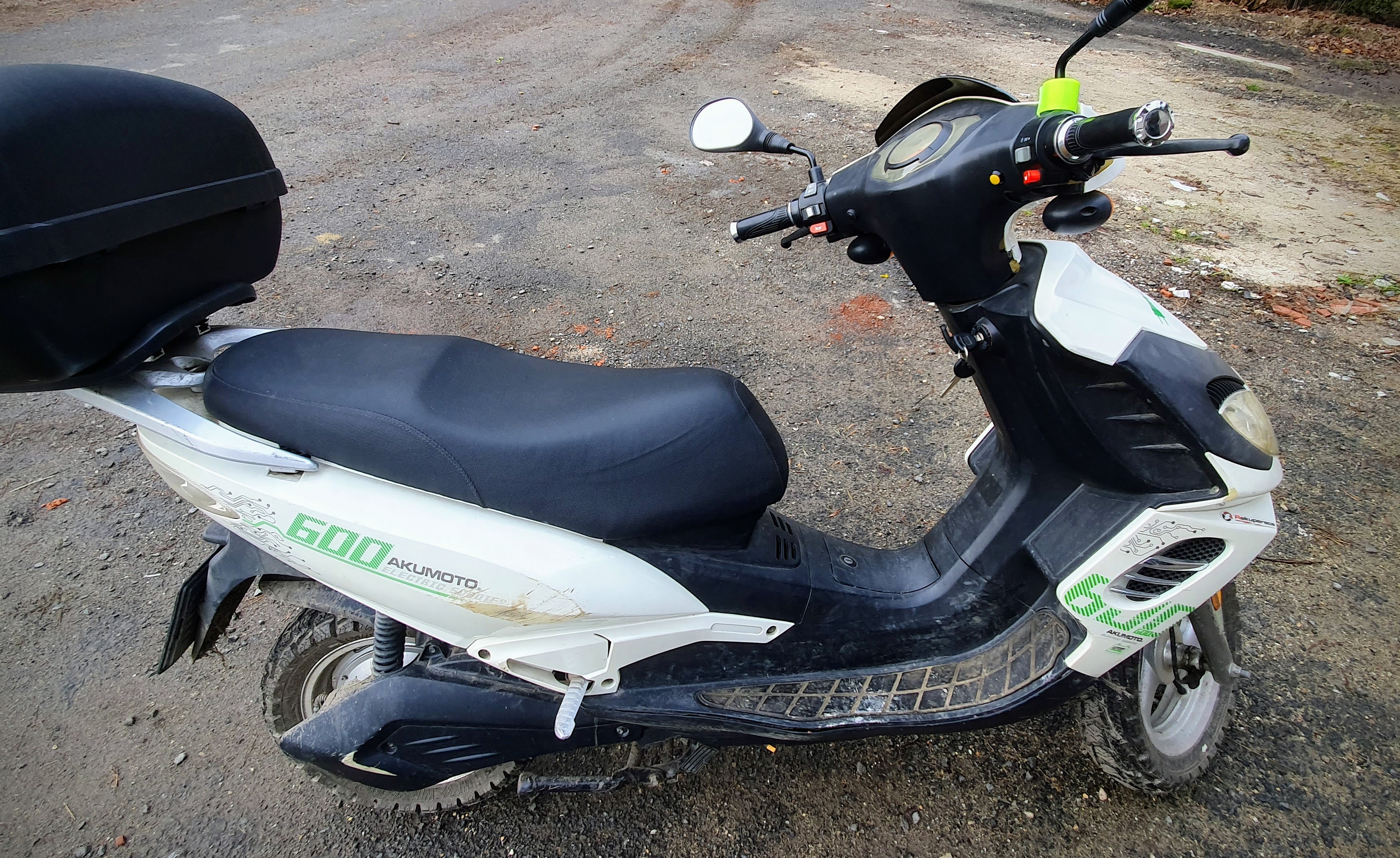
Complete configuration guide for an Hanscraft / Akumoto scooter using siliXcon SC controller with LYNX application.
Modifications:
- Original controller replaced with siliXcon SC
- Upgraded power cables to larger SIF gauge
- Custom DIY display integration
System Wiring
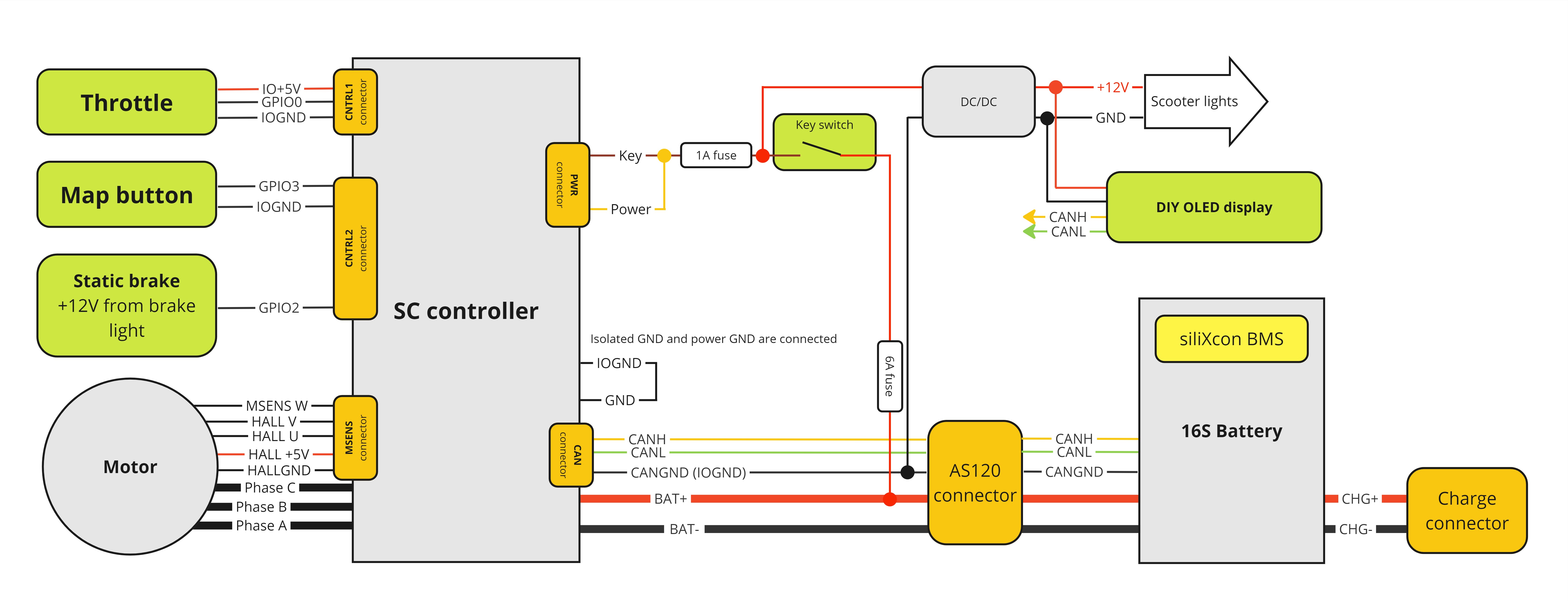
Special Configuration Notes:
- Controller lacks internal fuse (KEY and BAT+ unconnected internally)
- GND/IOGND connection possible inside controller (specific MPN upon order request)
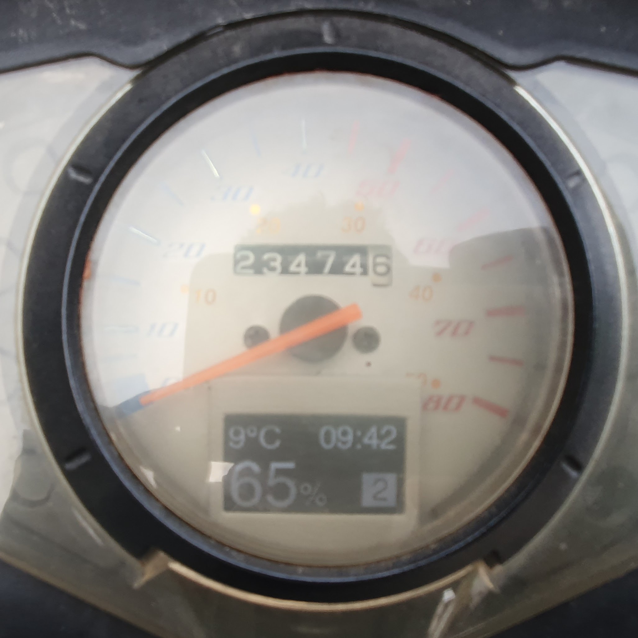
Display System
Custom display features:
- Current map indication
- Internet-synchronized time
- Air temperature (Dallas sensor)
- Battery SOC monitoring
- Home Assistant integration support
Technical Specifications:
- ESP32-based platform
- SH1106 128x64 OLED display
- CAN bus communication
- 12V power supply
- ESPHome firmware: Configuration
DIY Implementation Notice: This is a custom display solution without official siliXcon support. Implementation requires self-assembly and ESPHome knowledge.
System Configuration
Parameters not listed use default values
Motor Drive Parameters
Basic driver settings.
- Motor polepairs are needed to get the correct speed reading.
- Enable field weakening by increasing
fwcparameter value. This is needed for reaching higher speeds from the scooter. irefis set experimentally. After riding in summer in hot weather, motor temperature was observed. Theirefwas slowly increased until the motor temperature was acceptable.ipeakneeds to be higher thaniref, but lower than BMS short circuit current.- the
ipeakis negative to switch motor direction
- the
irefrsets maximum braking current. The value is negative.
"/driver/motor/pp" : "30" # '[pairs] pole pair count'
"/driver/dac/fwc" : "0.300000" # '[.iref] flux weakening current limit <0:disable>'
"/driver/iref" : "180.0" # '[A] reference phase current'
"/driver/irefr" : "-40.0" # '[A] brake phase current <0:disable>'
"/driver/ipeak" : "-250.0" # '[A] peak phase current (negative to switch direction)'
Motor parameters obtained from motor identification.
"/driver/motor/psi" : "0.017268" # '[Wb] PM flux linkage <0:ACIM> <eps:synRM>'
"/driver/motor/Rt" : "0.025072" # '[Ohm] resistance'
"/driver/motor/Ld" : "6.20675e-5" # '[Henry] D inductance'
"/driver/motor/Lq" : "6.55815e-5" # '[Henry] Q inductance'
"/driver/rest/hvar" : "5" # 'UVW hall sensor connection variant'
"/driver/rest/rangle" : "0.504701" # '[rad] sensor angle offset'
Battery limitation. The scooter uses siliXcon BMS and these parameters are overwritten by the BMS. But the default values are fall back.
"/driver/limiter/ibpos" : "130.0" # '[A] battery positive current limit <0:disable>'
"/driver/limiter/ibneg" : "-20.0" # '[A] battery negative current limit <0:disable>'
"/driver/limiter/ubmax" : "67.2000" # '[V] battery maximum voltage limit <0:disable>'
"/driver/limiter/ubmin" : "3.0" # '[V] battery minimum voltage limit <0:disable>'
"/driver/limiter/ubgain" : "0.100000" # 'battery voltage limiter gain'
Speed limitation parameters. It is necessary to tune these parameters. Wrong settings can cause oscillation or slow reaction.
"/driver/limiter/rdec" : "50.0" # '[RPM] speed limiter decrement rate'
"/driver/limiter/rgain" : "50.0" # 'speed limiter gain'
Speed reading
To make speed limitation work, it is necessary to set the speed reading. The speed is calculated from the motor speed.
gearthris in default value 1, because the scooter use hub motor and the gear ratio is 1:1.
"/odothr" : "704.0" # vartype: pr, desc: '[R/km] wheel revolutions per km'
Input setting
GPIO0 - is the accelerator input. Always use floating input for analog readings. GPIO1 - is the brake input. The input is direct +12V from the brake light. Use the pull-down to increase input tolerance from 10V to 12V GPIO3 - is map switch input.
Beepvol is set lover to reduce beeping.
"/common/ioconf0" : "0" # '<0:floating> <1:pull-up> <2:pull-down>'
"/common/ioconf1" : "2" # '<0:floating> <1:pull-up> <2:pull-down>'
"/common/ioconf3" : "1" # '<0:floating> <1:pull-up> <2:pull-down>'
"/common/beepvol" : "100" # 'common beep volume'
By default, GPIO0 is used as the accelerator. Other inputs must be configured.
The map and cruise share the same input. The map is activated by a short press. The cruise is activated by a long press. Value 19 means it is GDIN1. GDIN is digital representation of GPIO.
"/io/IN_mapswitch" : "19,0" # 'DIN ID'
"/io/IN_cruise" : "19,0" # 'DIN ID'
"/io/IN_sbrake" : "17,0" # 'DIN ID'
Accelerator settings
"/acc/csc/ldz" : "0.0" # vartype: pr, desc: 'lower deadzone'
"/acc/asc/min" : "1100" # vartype: pr, desc: '[mV,*] min of range'
"/acc/asc/max" : "4000" # vartype: pr, desc: '[mV,*] max of range'
"/acc/asc/center" : "2000" # vartype: pr, desc: '[mV,*]'
"/acc/asc/absmin" : "200" # vartype: pr, desc: '[mV,*] lowest valid'
"/acc/asc/absmax" : "4800" # vartype: pr, desc: '[mV,*] highest valid'
"/acc/acc_opts/thr_curr_offset" : "0.0" # vartype: pr, desc: 'Used only in voltage mode. 0 -> imult is scaled same as current'
"/acc/acc_opts/VLT_enter_margin" : "0.05" # vartype: pr
"/acc/acc_opts/CUR_enter_margin" : "0.150000" # vartype: pr
"/acc/acc_opts/smooth_lpf" : "0.100000" # vartype: pr, desc: '[lpf] smooth acceleration start, adds lpf to imult, umult <1 : disabled>'
Brake settings
Brake switch (static brake)
Using these parameters are tuned engaging and disengaging of the static brake.
"/brake/rgnslup" : "0.002000" # vartype: pr, desc: 'static brake rise rate'
"/brake/rgnsldn" : "0.030000" # vartype: pr, desc: 'static brake fall rate'
Combrake (combined brake - braking from accelerator)
To make combined brake work, you need to set set /acc/asc/center.
Value 19 = 1 + 2 + 16
- 1 - brake doesn't disarm
- 2 - comlvl enable
- 16 - auto-hold
"/drvopts" : "19" # vartype: pr, desc: '|1:brake doesn't disarm| |2:comlvl enable| |4:brake combined mode| |8:brake comb disable reverse| |16:auto-hold| |32:auto-brake|'
Maps settings
In the scooter are used 2 maps. The first map is for speeds up to 46km/h. The second map is for speeds up to 70km/h.
Maximum torque is the same in both maps. Only power and speed are different.
"/maps/mapcnt" : "2" # vartype: pr, desc: 'no of maps'
"/maps/initmap" : "-1" # vartype: pr, desc: 'initial map number <-1 : Restore last map>'
"/maps/kphlimit" : "75.0" # vartype: pr, desc: 'max speed for maps'
"/maps/pwrlimit" : "5000.0" # vartype: pr, desc: 'max pwr for maps'
"/maps/map0/kph" : "75.0" # vartype: pr
"/maps/map0/pwr" : "5000.0" # vartype: pr
"/maps/map1/kph" : "46.0" # vartype: pr
"/maps/map1/pwr" : "3000.0" # vartype: pr
"/maps/map1/trqlvl" : "1.0" # vartype: pr
"/maps/map1/comlvl" : "0.800000" # vartype: pr
"/maps/map1/sbrakelvl" : "1.0" # vartype: pr
"/maps/map2/kph" : "70.0" # vartype: pr
"/maps/map2/pwr" : "5000.0" # vartype: pr
"/maps/map2/trqlvl" : "1.0" # vartype: pr
"/maps/map2/paslvl" : "0.0" # vartype: pr
"/maps/map2/comlvl" : "0.800000" # vartype: pr
"/maps/map2/sbrakelvl" : "1.0" # vartype: pr
Misc
Enable warning beep and auto shutdown.
"/misc/warntim" : "30" # vartype: pr, desc: '[s] time to warning sound'
"/misc/shdntim" : "600" # vartype: pr, desc: '[s] time to shutdown'
BMS
Receiving CAN messages from siliXcon BMS needs to be enabled. The BMS sends SOC. This is used for the battery gauge on display.
"/bms/bmstype" : "1" # vartype: pr, desc: 'Type of BMS: <0:disabled> <1:siliXcon> <10:kortanek> <20:Jikong> <30:akuenergy>'