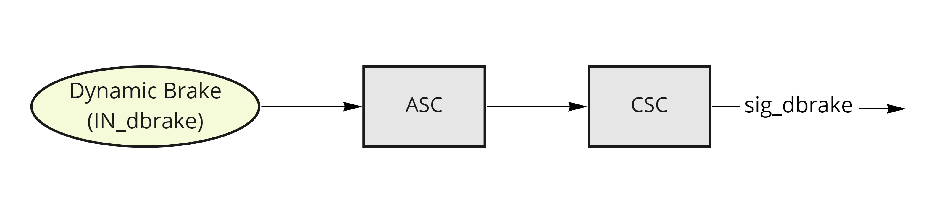
Dynamic Braking System
Processes analog brake input through ASC block (converts mV to 0-1 range) and CSC block (applies filtering and deadzones). Configuration blocks located in /brake/asc and /brake/csc folders.
Setup Process
Input Configuration
Select brake input pin by setting /io/IN_dbrake to appropriate GPIO ID.
Common GPIO assignments:
| GPIO ID | Input |
|---|---|
| 8 (default) | GPIO0 |
| 9 | GPIO1 |
| 10 | GPIO2 |
| 11 | GPIO3 |
| 12 | GPIO4 |
See Input mapping for details.
Configure GPIO as floating input: set /common/ioconfX to 0. GPIO details
Brake Force Configuration
Brake signal controls driver command level, with /driver/irefr setting phase current reference. Details on brake current
Signal Range Setup
Similar to accelerator configuration: Getting Started Guide
Key ASC parameters (/brake/asc):
min: Minimum signal levelmax: Maximum signal level
CSC parameters (/brake/csc):
ldz: Lower deadzone (default 10%)hdz: Upper deadzone (default 10%)
Monitor dynamic brake level via /brake/sig_dbrake
Accelerator Integration
Control accelerator-brake interaction via drvopts. Parameter details
Operating Modes
-
Standard Mode (
drvopts= 0)- Brake overrides accelerator
- Immediate accelerator disable on brake activation
-
Reverse Enable (
drvopts= 5)- Combines brake and accelerator signals
- Negative values enable reverse
- Equal inputs cancel (motor freewheels)
-
Fusion Mode (
drvopts= 13)- Combines brake and accelerator signals
- Negative values trigger braking
- Equal inputs cancel (motor freewheels)