Input Mapping
Lynx enables mapping of logical inputs to physical inputs on specific devices, providing flexible hardware configuration options.
All referenced variables are located in the /io folder.
Input Parameter List
| Parameter | Description | Input Type |
|---|---|---|
in_acc | Primary accelerator signal input | Analog input |
in_acc_2 | Secondary accelerator signal input | Analog input ID for 2-channel accelerator Digital input ID for endstop switch |
in_cadence | PAS cadence input | Digital input ID |
in_clutch | Clutch input | Analog input ID |
in_cruise | Cruise control activation input | Digital input |
in_dbrake | Dynamic brake input | Analog input ID |
in_light | Light control input | Digital input |
in_maplock | Secondary map set activation input | Digital input |
in_mapswitch | Map selection input | Digital input |
in_reverse | Reverse mode activation input | Digital input |
in_sbrake | Static brake activation input | Digital input |
in_speed | External speed sensor input | Analog input ID for SX,SL,SC Digital input ID for AX, AM |
in_torque | Torque sensor input | Analog input ID |
in_lock | Lock function input | Digital input |
in_seatswitch | Seat switch input | Digital input |
Parameter Values
Input parameters consist of two-value arrays: Physical input ID and Input options.

Physical Input ID
Physical input ID identifies the specific physical input on the device, linking logical inputs to hardware inputs. Available IDs are listed here: Input ID documentation
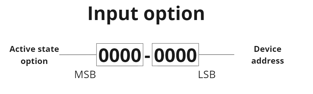
Input Options
Input options combine two components: 4 MSB bits for Active state option and 4 LSB bits for device address.
Device Address
Addressing functionality is pending implementation. Currently, always use address 0 for your device.
Active State
Active state options apply only to digital inputs.
This option defines which GDIN state is interpreted as True. By default (active state 0), any non-zero GDIN value is considered true.
| True Condition | Physical State | Input Option (DEC) | Input Option (BIN) |
|---|---|---|---|
| GDIN value is NOT 0 | Connected to any voltage or GND | 0 | 0b0000 0000 |
| GDIN value is NOT 1 | NOT connected to +3V | 16 | 0b0001 0000 |
| GDIN value is NOT 2 | NOT connected to +5V | 32 | 0b0010 0000 |
| GDIN value is NOT 3 | NOT connected to +10V | 48 | 0b0011 0000 |
| GDIN value is NOT -1 | NOT connected to GND* | 112 | 0b0111 0000 |
| GDIN value is 0 | NOT connected to any voltage/GND | 128 | 0b1000 0000 |
| GDIN value is 1 | Connected to +3V | 144 | 0b1001 0000 |
| GDIN value is 2 | Connected to +5V | 160 | 0b1010 0000 |
| GDIN value is 3 | Connected to +10V | 176 | 0b1011 0000 |
| GDIN value is -1 | Connected to GND* | 240 | 0b1111 0000 |
* Requires activated internal pull-up
Special Input Values
| Value | Description |
|---|---|
3,14 | Bafang display - lights on |
5,14 | Bafang display - walk mode on |
X,255 | Use input from CAN message 0x5FF |
X,254 | Use input from VDS display button |
16,6* | siliXcon VDS display GDIN 0 |
17,6* | siliXcon VDS display GDIN 1 |
18,6* | siliXcon VDS display GDIN 2 |
* You can use together with Active state options
siliXcon VDS display button input settings
It is possible to map buttons from the VDS display to inputs in the LYNX application. The address of the input is 254 and the first value of the input is button event selector.
| Button event selector | Description |
|---|---|
0,254 | Button 1 status |
1,254 | Button 2 status |
2,254 | Button 3 status |
3,254 | Button 4 status |
4,254 | Button 1 long press status |
5,254 | Button 2 long press status |
6,254 | Button 3 long press status |
7,254 | Button 4 long press status |
8,254 | Button 1 short press event |
9,254 | Button 2 short press event |
10,254 | Button 3 short press event |
11,254 | Button 4 short press event |
12,254 | Button 1 long press event |
13,254 | Button 2 long press event |
14,254 | Button 3 long press event |
15,254 | Button 4 long press event |
16,254 | Button 1 short press release event |
17,254 | Button 2 short press release event |
18,254 | Button 3 short press release event |
19,254 | Button 4 short press release event |
20,254 | Button 1 long press release event |
21,254 | Button 2 long press release event |
22,254 | Button 3 long press release event |
23,254 | Button 4 long press release event |