Display Systems
info
All parameters located in misc folder
UARTCOM interface supports displays and programmable LEDs for:
- Ride data (speed, map, battery)
- Input status (map switch, walk assist, lights)
| Parameter | Function | Options |
|---|---|---|
dispmode | Display type | -1: Auto-detect 0: Disabled 1: Bafang 3: 800U 4: KT-LCD3 32+: WS LED |
ledbright | WS LED intensity | 0-100% |
ledopts | WS LED configuration | Bits 0-2: Color order Bit 4: Disable while driving Bit 8: Dim while riding |
Compatible Displays
warning
Display compatibility depends on manufacturer protocols. Protocol changes may affect functionality.
tip
Additional display support available upon request.
Supported Models
-
Bafang UART (
dispmode= 1)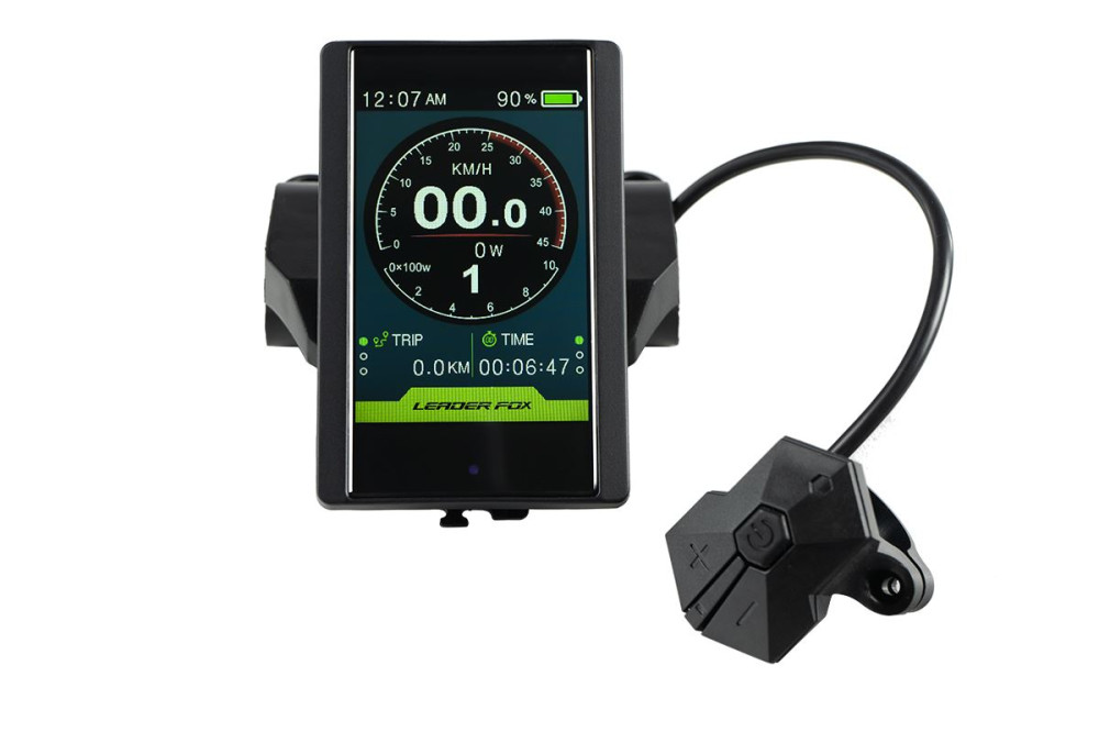
-
800U UART (
dispmode= 3)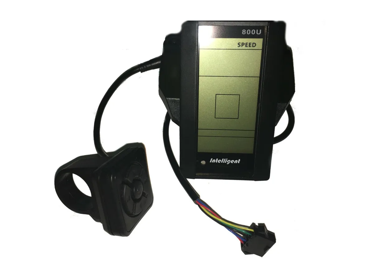
-
KT-LCD3 UART (
dispmode= 4)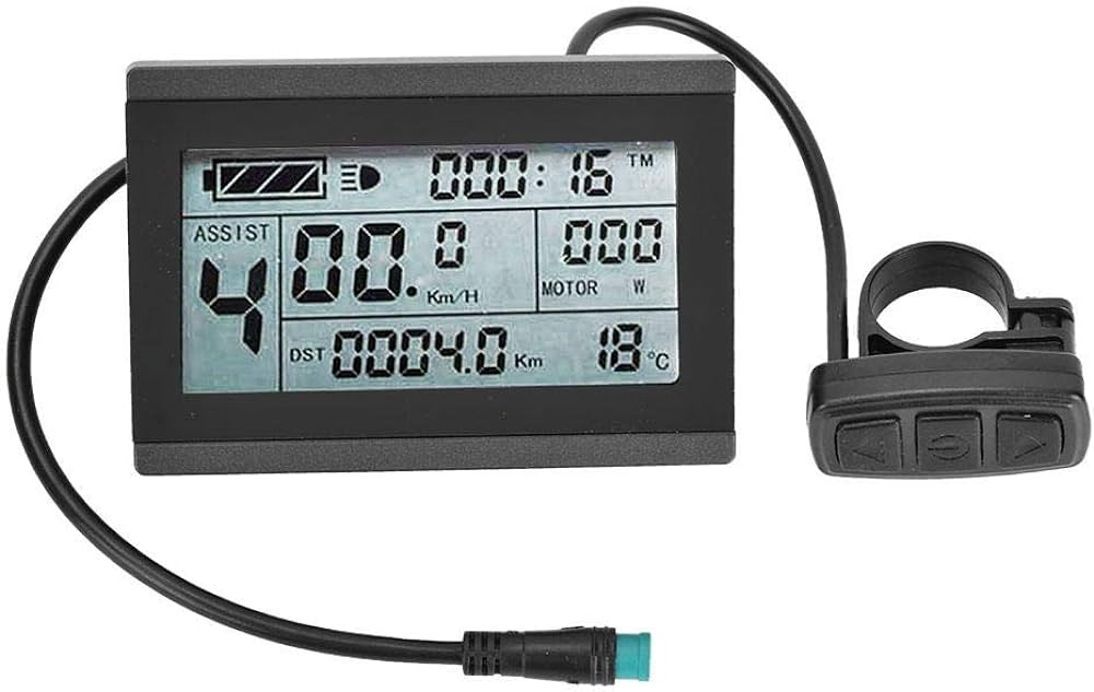
WS LED Configuration
Compatible with WS281x LED series.
Installation
- Connect LED data to UARTCOM TX
- Ground to IOGND
- Power options:
- UARTCOM +5V (within current limits)
- External power supply
- Adjust brightness via
ledbright
warning
Verify LED current draw against controller specifications
LED Modes
Basic Map Display (32)
Single LED indicating:
- Pulsing: Disarmed
- Solid color: Armed
- Green: Map 1
- Blue: Map 2
- Red: Map 3
- White: Other maps
Status Display (40)
Priority order:
- Temperature warning (purple)
- Map change (10s color display)
- Battery level (green→red gradient)
- Low battery warning (< 30%, blinking red)
Multi-LED Display (50-59)
- First LED: Map indicator
- Additional LEDs: Battery bar graph
- Configuration range: 1-10 LEDs total
Temporary Map Display (70)
- Shows map color for 15s after change
- Auto-off afterward