Accelerator Configuration Basics
Disambiguation
The term 'throttle' originates from gas/combustion engines, where it refers to a control element for acceleration. As we transition to electric vehicles, we prefer the term 'accelerator'. Both terms can be used interchangeably as synonyms.
tip
Review these concepts first:
Accelerator Operation
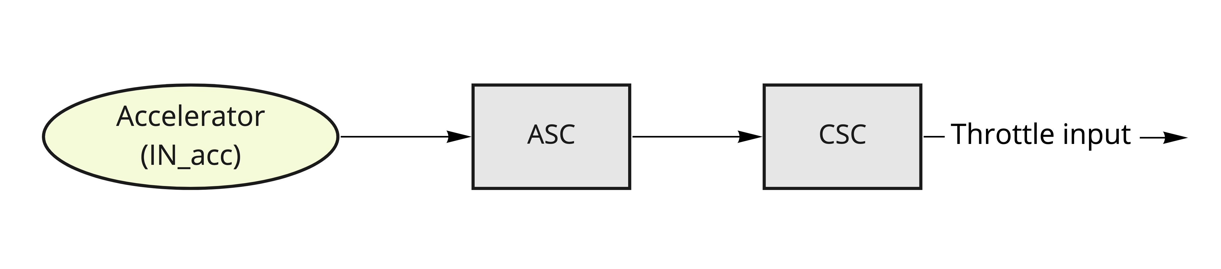
Analog accelerator input processing occurs in two stages:
- ASC block: Converts input signal from [mV] to normalized 0-1 value
- CSC block: Applies signal conditioning (low pass filter, deadzones)
Signal flow diagram:
Setup Process
Input Pin Assignment
Set /io/IN_acc to the appropriate GPIO ID.
Common GPIO assignments:
/io/IN_acc Value | Input Pin |
|---|---|
| 8 (default) | GPIO0 |
| 9 | GPIO1 |
| 10 | GPIO2 |
| 11 | GPIO3 |
| 12 | GPIO4 |
See Input mapping for details.
warning
Configure GPIO as floating input by setting /common/ioconfX to 0. GPIO configuration details
Signal Range Configuration
tip
Reference Getting started - accelerator for initial setup
Adjust /acc/asc parameters:
min: Minimum accelerator signalmax: Maximum accelerator signal
Deadzone settings in /acc/csc:
- Default: 10% deadzone at signal extremes
ldz: Lower deadzonehdz: Upper deadzone