Redundant Accelerator System
The term 'throttle' originates from gas/combustion engines, where it refers to a control element for acceleration. As we transition to electric vehicles, we prefer the term 'accelerator'. Both terms can be used interchangeably as synonyms.
Two redundancy options available for enhanced Ride-by-Wire safety:
- Dual analog signal accelerator
- Single analog signal with end-stop switch
Either configuration sets sig_acc to NaN on error, triggering vehicle disarm. Recovery behavior controlled by safetyopts parameter - default setting maintains disarm until power cycle.
Parameters located in /acc folder
Test system with single accelerator before implementing redundancy to isolate potential issues.
Configuration Parameter
dual_err
- 0:1 - Error threshold for dual analog signals
- -1 - Enables end-stop switch monitoring
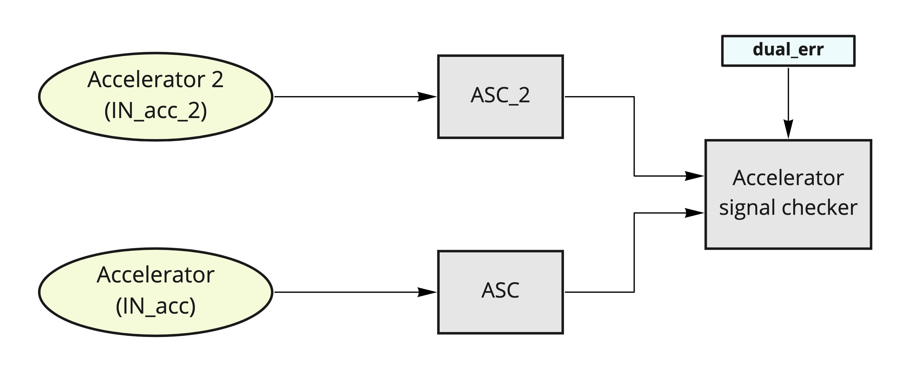
Dual Analog Implementation
Compares primary and secondary accelerator signals (post-ASC processing). Disables acceleration if signal difference exceeds dual_err threshold.
Setup Process
- Configure inputs:
- Monitor via Scope:
/acc/asc/out,/acc/asc_2/out,/acc/acc_err - Adjust ASC values for signal matching (minimize
acc_err) - Set
dual_errslightly above maximum observedacc_err
End-Stop Switch Implementation
Monitors single analog signal with end-stop switch. Disarms if accelerator value exceeds dual_err when end-stop activated.
Setup Process
Note distinction between GPIO ID and GDIN ID
- Configure inputs:
- Monitor via Scope:
/acc/asc/out,/acc/acc_err - Note
/acc/asc/outvalue at end-stop activation - Set
dual_errto negative of noted value - Verify
acc_errremains zero during operation
Input ID Reference
See Input mapping for details.
| GPIO ID | Input |
|---|---|
| 8 (default) | GPIO0 |
| 9 | GPIO1 |
| 10 | GPIO2 |
| 11 | GPIO3 |
| 12 | GPIO4 |
Configure GPIO as floating input: set /common/ioconfX to 0. GPIO details
| GDIN ID | Input | Type |
|---|---|---|
| 16 | GDIN0 | |
| 17 | GDIN1 | |
| 18 | GDIN2 | |
| 19 | GDIN3 | |
| 20 | GDIN4 | |
| 32 | DIN1 | uint8 |
| 33 | DIN2 | uint8 |
| ... | ... | |
| 39 | DIN8 | uint8 |
- End-stop compatible with GDIN or DIN
- Enable pull-up for end-stop: set
/common/ioconfXto 1. GPIO details