Welding
The controller can be used for stick (arc) welding. Simply connect the welding electrode holder to the controller and set the welding current.
This feature is particularly useful if you have a farm and need to weld something in the field while having an electric bike with a siliXcon controller.
This feature is only available in the VECTOR_LYNX_welding version. Due to memory constraints, it may not be compatible with all controller versions. This version is currently not publicly available. Contact support for more information about accessing this feature.
Capabilities
- Welding current control (via external potentiometer) up to the controller's maximum current
- Anti-stick (customizable parameters)
- Hot-start (customizable parameters)
How to Use This Feature
- Turn off the device
- Connect the welding electrode holder to the controller
- Hold the welding button
- Turn on the device and wait at least 2 seconds
- Release the welding button
- Set the welding current using the external potentiometer
- Begin welding
When welding is active:
- LYNX mode is set to 30
- SiliXcon VDS display will show welding mode
- Future versions may display welding statistics - Let us know what information you'd like to see!
Wiring
Welding Enable Button:
This button activates welding mode. It can share functionality with another button, such as the map button. This means /io/IN_mapswitch will have the same value as /welding/IN_enable_welding.
Welding Current Potentiometer:
This optional input controls welding current. Without this input or potentiometer connection, the controller uses the default_cmd value.
Welding Electrode Holder:
To connect the holder, disconnect motor phase B from the controller. Connect the holder to the free motor phase and the ground clamp to the controller phase B output.
- Always connect clamps before entering welding mode. Otherwise, welding current will flow through the motor. While this won't damage the motor or controller, it may cause motor rotation and overheating.
- Always use a motor temperature sensor. The controller will reduce current if the motor overheats to prevent damage.
During welding, current flows through the motor, which acts as inductance. Since the vehicle is stationary, there's no airflow for motor cooling. This results in lower welding current compared to normal driving current.
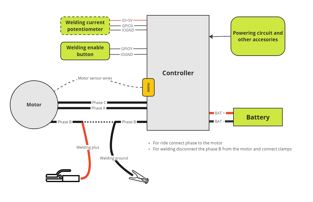
All other wiring remains the same as in normal controller operation. Accelerator, brake, and other inputs/outputs can be connected as usual.
Parameters
Welding features can be customized through parameters, including maximum current, anti-stick, hot-start, and other settings.
All parameters are located in the /welding folder.
| Parameter | Description |
|---|---|
max_curr | [A] Maximum current for the welding |
default_cmd | [0-1] Default command for welding. This is used if the current potentiometer is not used or connected. |
cmd_lpf | Low-pass filter for the welding command |
IN_enable_welding | GDIN value for the welding enable button. Check input mapping for more info |
IN_curr_set | GPIO value for potentiometer. Check input mapping for more info |
delay | [ms] this serves two purposes: - Delay before anti-stick is enabled - Duration of the hot-start |
antistick_voltage | [V] Voltage for the anti-stick. If the voltage is lower than this value (for delay period), the controller will reduce the current to 10%. |
hotstart_voltage | [V] Voltage for the hot-start. If the voltage is higher than this value (for delay period), the controller will increase the current by hotstart_cmd_mult |
hotstart_cmd_mult | [0-1] Multiplier for the hot-start. If the voltage is higher than hotstart_voltage, the current will be multiplied by this value. |
asc | ASC block for the current poteintiometer input. If the output of the asc is NaN, the controller will use the default_cmd value. (ie. Input voltage is below /asc/absmin) |
| State | Description |
|---|---|
welding_state | 1: normal operation 2: antistick active 3: hotstart active |
voltage | [V] Voltage on the arc |
- If you want to see the actual current, plot the
/driver/motor/currentqf. - If you want to invert the voltage on the clamps, configure reverse switch
/io/IN_reverse, which will invert the voltage on the clamps if enabled.