III. Accelerator Configuration
The term 'throttle' originates from gas/combustion engines, where it refers to a control element for acceleration. As we transition to electric vehicles, we prefer the term 'accelerator'. Both terms can be used interchangeably as synonyms.
This section covers accelerator range calibration and also demonstrates SWTools functionality to help with further steps.
This configuration is optional
Default values are typically sufficient, though you may notice significant deadbands at accelerator extremes.
The objective here is to measure accelerator analog input values at minimum and maximum positions, then configure these as range parameters.
We will determine the values of /acc/asc/min and /acc/asc/max.
Accelerator analog readings (in [mV]) are available in two locations:
/acc/asc/instate/common/gpio0state (GPIO0 is mapped as accelerator input by default)
Motor Deactivation
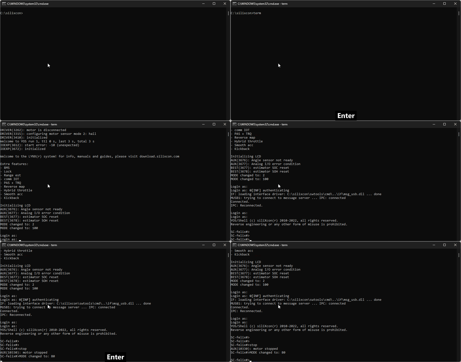
First, disable the motor using the stop command. This suspends LYNX drive control until either power cycle or run command execution.

Signal Visualization
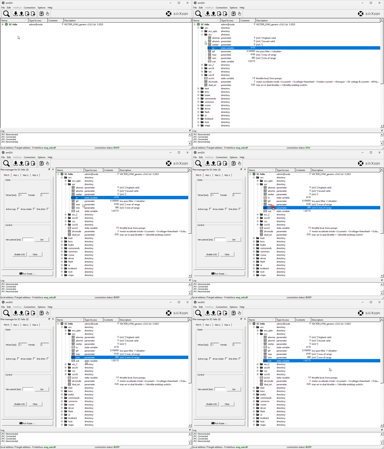
Use the scope tool to monitor accelerator signals:
- Launch Scope
- Configure Plot 0:
/acc/asc/min- accelerator minimum/acc/asc/max- accelerator maximum/acc/asc/in- raw accelerator reading [mV]
- Configure Plot 1:
/acc/asc/out- normalized accelerator reading [0-1]

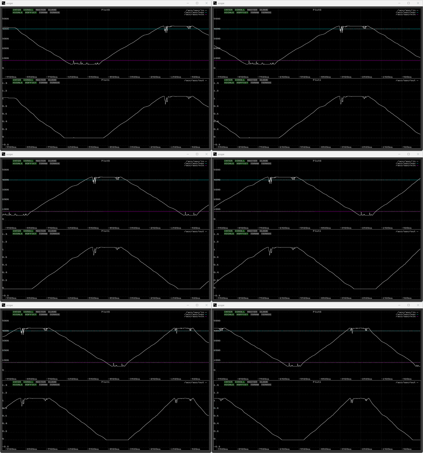
Scope Analysis
Signal noise indicates potential wiring or sensor issues. Use scope monitoring to diagnose vehicle input problems.

Range Configuration
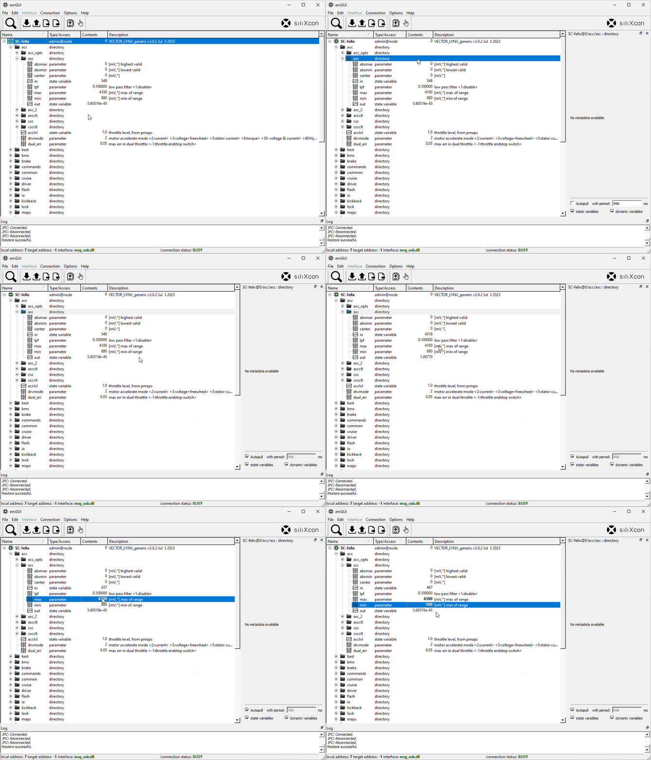
- Access
/ascfolder (right-click → Open) - Enable
Autopullfor automatic value updates - Move accelerator through full range
- Spot the minimum/maximum values
- Set
/acc/asc/minand/acc/asc/maxaccordingly

Motor Reactivation
Test new settings by either:
- Executing
runcommand for immediate activation - Power cycling after saving parameters
The motor then resumes LYNX control (for accelerator response verification).