Signal flow
Signal path settings
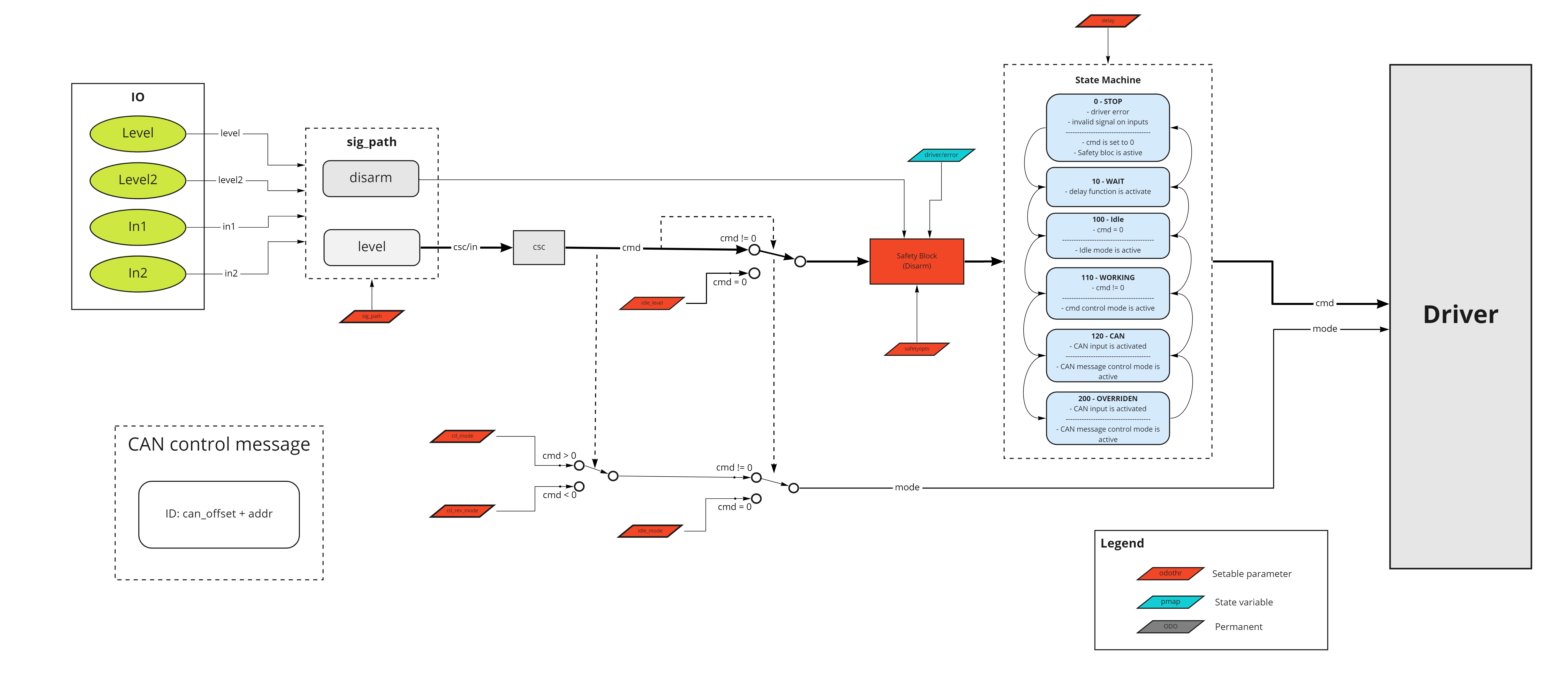
The signal path processing block is positioned between the inputs and the main block. It processes 2 analog inputs (level1 and level2) and 2 digital inputs (in1 and in2).
Signal path block takes 5 arguments:
sig_pathparameter - an integer value selecting the desired schemelevel1- value of the first analog inputlevel2- value of the second analog inputin1- value of the first digital inputin2- value of the second digital input
and produces 2 outputs:
output_level- analog value that will be converted to cmd using csc.disarm- binary value (0/1); if set to 1 and disarming is enabled in parameters, the motor won't rotate even iflevelis non-zero.
You can select one of the following schemes by setting the sig_path parameter in the controller. If sig_path is set to any unspecified value, the controller behaves as if sig_path were set to zero.
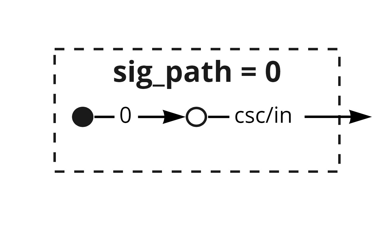
sig_path = 0
No inputs are mapped to the control block. This setting is useful when you want to control the motor directly through the driver API.
output_levelis always0, regardless of inputs.disarmis irrelevant sincelevelis always zero.
To completely disable the OPHION application, set parameter /common/appsel to 10.
This setting prevents startup audio notification and disables the mode switch functionality.
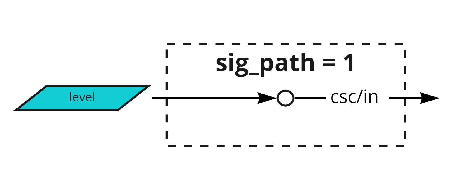
sig_path = 1 - default
This default setting maps one analog input to the cmd.
output_levelequalslevel1.disarmis always zero.
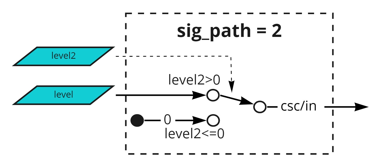
sig_path = 2
Similar to sig_path = 1, but includes a safety check via level2.
output_levelequalslevel1only whenlevel2 >= 0; otherwise,output_levelis zero.disarmis always zero.
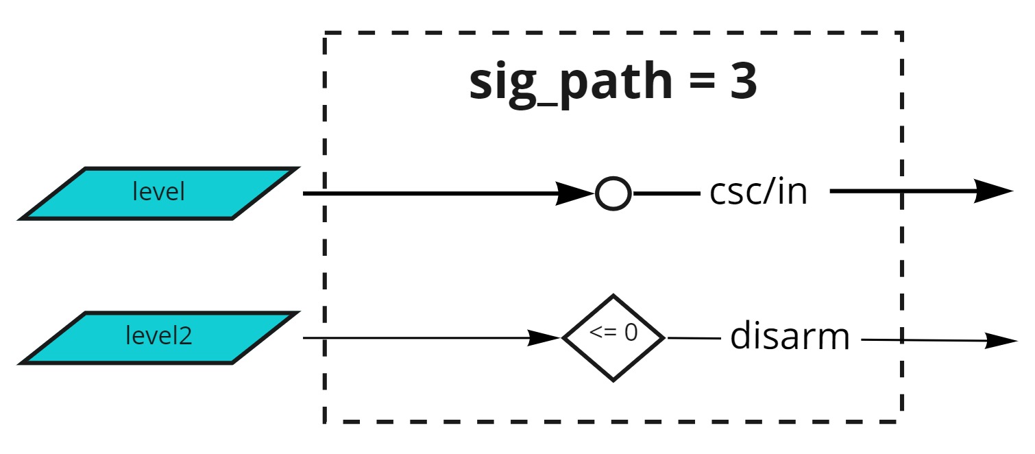
sig_path = 3
Identical to sig_path = 1, but with disarm functionality.
output_levelequalslevel1.disarmis1whenlevel2 <= 0and0otherwise.
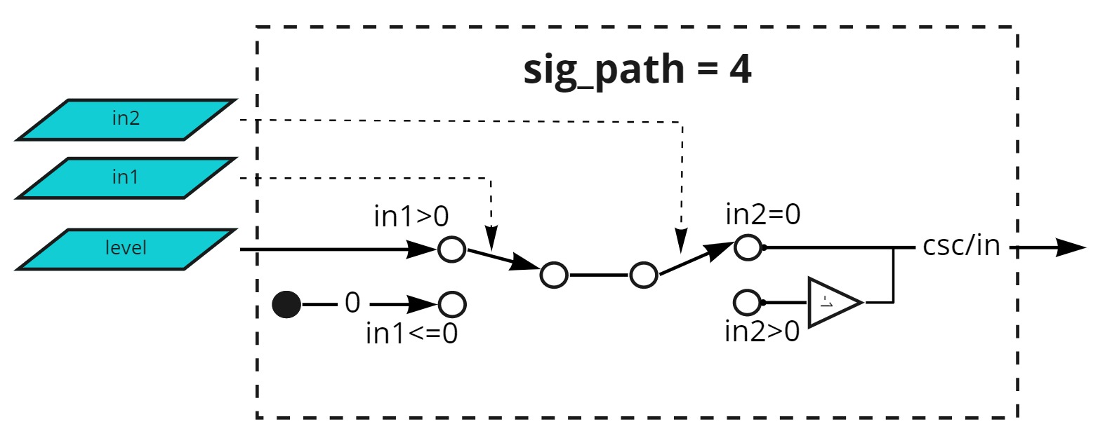
sig_path = 4
output_levelequalslevel1whenin1 = 1(enable switch), otherwise zero. The value is multiplied by-1(reverse switch) whenin2 = 1.disarmis always zero.
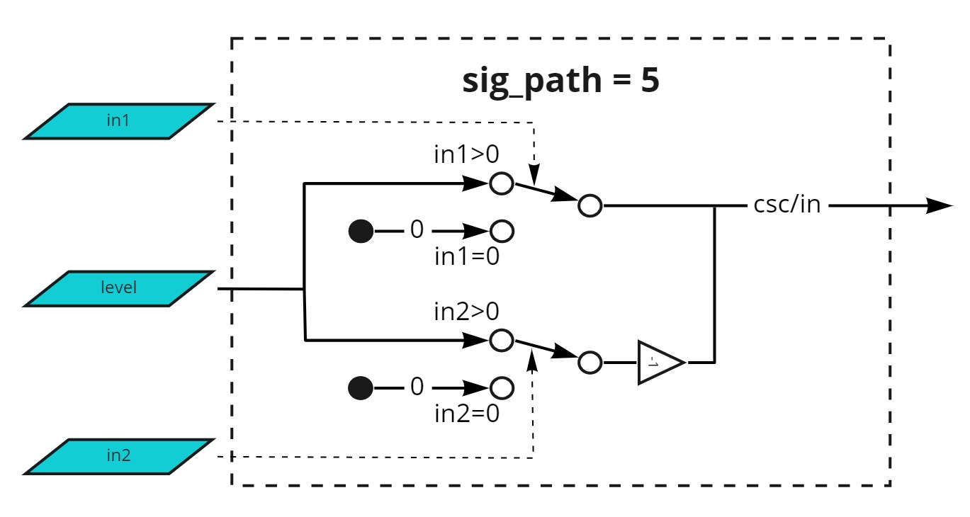
sig_path = 5
level1 sets the desired level_output value, while in1 acts as forward switch and in2 as backward switch.
output_levelis determined as follows:- When
in1is enabled:output_levelequalslevel1 - When
in2is enabled:output_levelequals-level1 - When neither is enabled:
output_levelis zero - When both are enabled:
output_levelequalslevel1
- When
disarmis always zero.
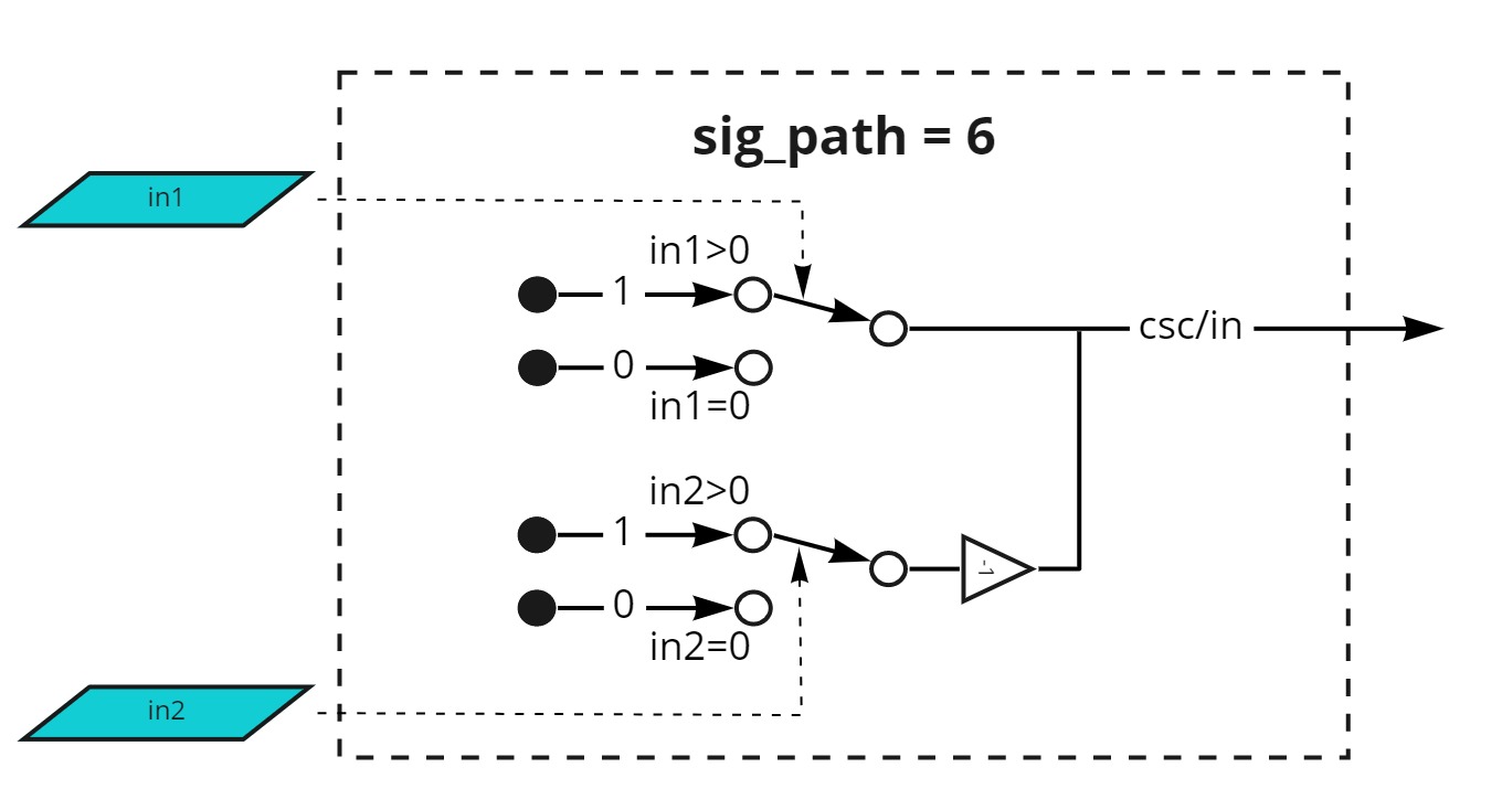
sig_path = 6
Functions like sig_path = 5, but assumes level1 is always 1.
output_levelis determined as follows:- When
in1is enabled:output_levelequals1 - When
in2is enabled:output_levelequals-1 - When neither is enabled:
output_levelis zero - When both are enabled:
output_levelequals1
- When
disarmis always zero.
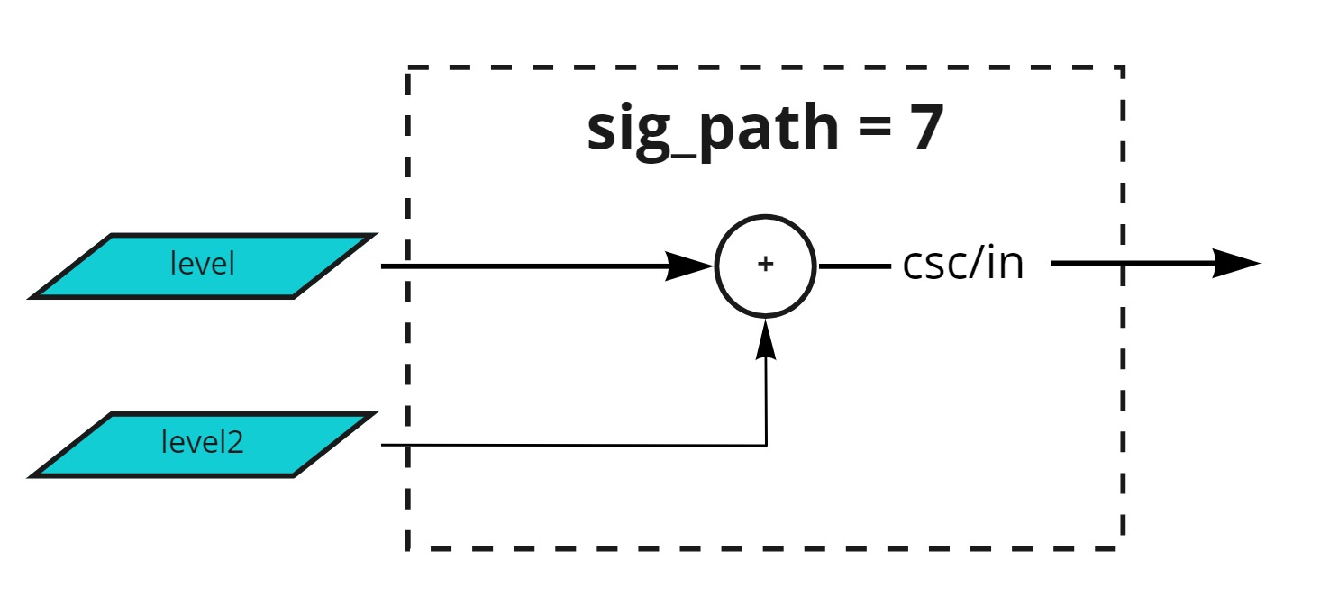
sig_path = 7
output_levelequalslevel1 + level2.disarmis always zero.