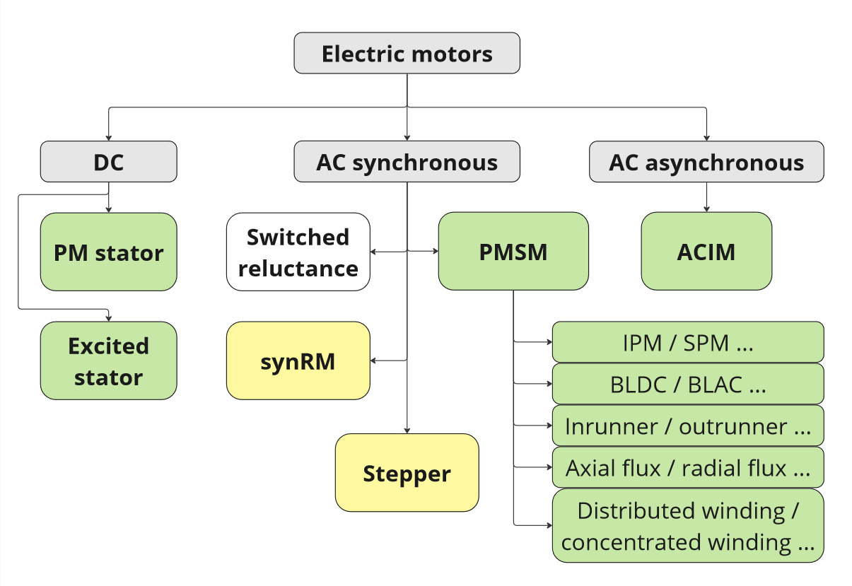
Motor types
Electric motors can be divided into several categories. Our ESCx controllers primarily target the types marked in green, while others have marginal support.
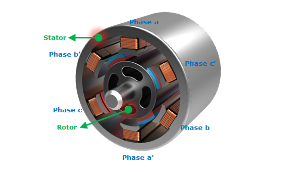
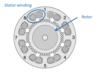
Each motor consists of two main parts:
- Stator: The stationary part that doesn't move. In synchronous and induction motors, the winding is located here. For DC motors, magnets are typically placed in the stator.
- Rotor: The rotating part of the motor. In synchronous motors (except reluctance motors), magnets are located here. The winding is found here in DC and induction motors. In induction motors, this winding is called a squirrel cage.
PMSM
PMSM (permanent magnet synchronous machine) is the primary target motor group for our ESCx controllers, where the controller replaces the mechanical commutator with an algorithmic alternative. Common features of PMSM motors include:
- Winding in the stator and magnets in the rotor. ESCx supports three phase systems only (and multiplies of three). For other configurations, please contact us.
- Voltage proportional to RPM and current proportional to generated torque in linear mode (without flux alteration).
- Induced voltage (back-EMF) that is proportional to motor speed in both amplitude and frequency.
The permanent magnet synchronous motors can usually be further classified according to:
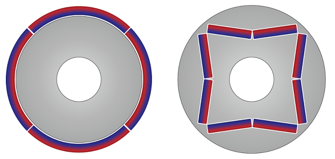
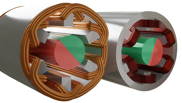
- SPM (left) - IPM (right) (rotor magnet placement): IPMs can achieve wider speed-torque ranges through reluctance torque and field weakening, but require more complex control:
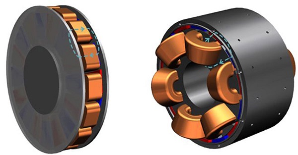
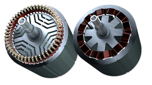
- inrunner (left) - outrunner (right) (rotor construction): Outrunners excel in direct-driving low-speed loads where gearboxes aren't suitable (like props or wheel hubs), but tend to be heavier, present cooling challenges, and have higher inertia:
- axial (left) - radial (right) (flux orientation): Axial flux motors offer an interesting alternative in terms of better thermal management but require precise rotor construction. Suitability depends on application requirements:
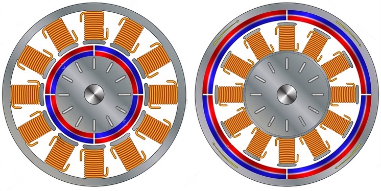
- distributed (left) - concentrated (right) (winding architecture): Distributed windings are preferred for high-speed applications due to lower eddy current losses, though in smaller motors, large winding arcs increase ohmic losses:
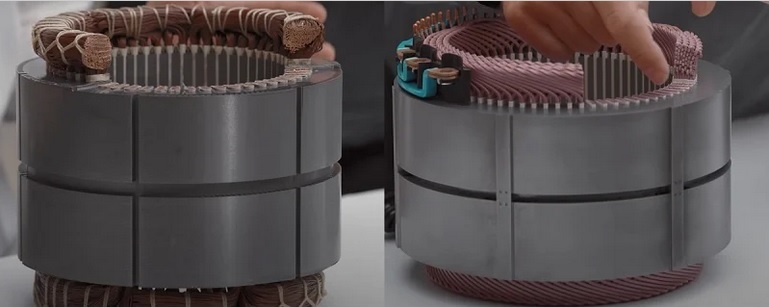
- stranded (left) - hairpin (right) (winding technology). Hairpin windings provide better copper fill and easier manufacturing, but at high speeds, the rectangular conductor's skin effect reduces efficiency:
There is a plenty of literature and ongoing research around these types and other marginal configurations. But from the electrical and control perspective, the behavior is pretty much similar for all of them. Let's break down the more significant classification for us, that is BLAC-BLDC :
BLDC
BLDC (brushless DC motor) shares similar construction with BLAC motors but has distinct characteristics.
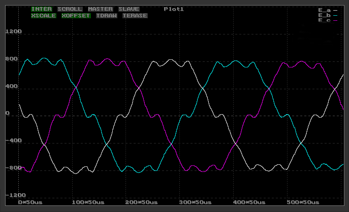
The induced voltage (Back-EMF) has a trapezoidal shape due to a lower winding factor and specific mechanical construction features. If these three trapezoidal curves were rectified, they would produce smooth DC voltage without ripple. The controller performs this rectification, acting as an electronic commutator.
BLDC motors are typically driven with block commutation control, where voltage, RPM, current, and torque relationships resemble those of DC motors. At any given moment, only two of three phases are connected, with the third disconnected. The controller manages the sequence as the rotor turns, creating a magnetic field that drives the rotor magnets to generate torque. This electronic commutation is why BLDC motors are also called electronically commutated motors.
Nothing really prevents a motor with non-sinusoidal back-EMF to be successfully driven with the FOC algorithm. Nevertheless, some caution must be taken, namely that the higher harmonic disturbances might become coupled to the DC-side (unless compensated by the algorithm). Also, in the case of active flux control (e.g. within IPM motor driving), the back-EMF tends to change the shape and usually become more sinusoidal. Please contact siliXcon for those advanced guidelines.
BLAC
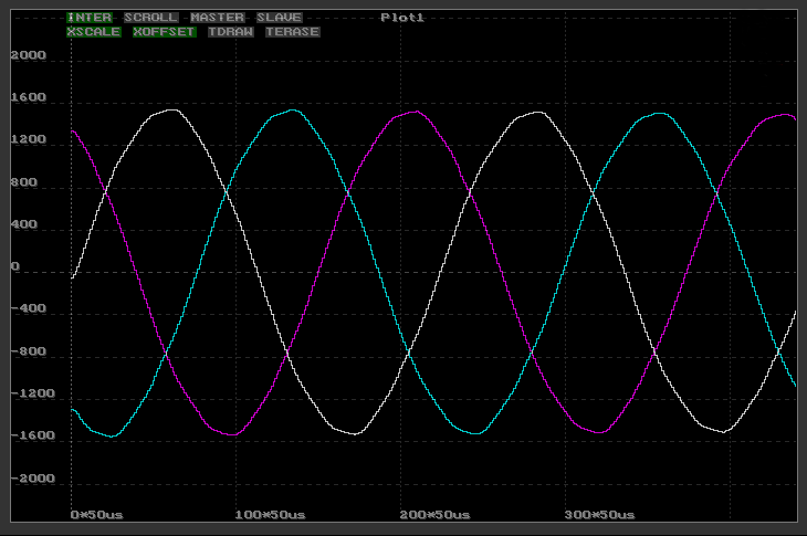
BLAC (brushless AC motor) shares similar construction with BLDC motors but produces sinusoidal back-EMF due to a higher winding factor and specific mechanical construction features.
BLAC motors typically employ vector drive or FOC (Field-Oriented Control) algorithms, where all three phases are switched to either positive or negative rail during active control. The controller makes algorithmic transformation of all electric quantities into rotor coordinates and back, separating them into magnetizing and torque-generating DC components, effectively producing a continuous alternative of the discrete commutation. Without this coordinate transformation, phase current measurements only show the geometric sum of these components. The controller's power stage switches create sinusoidal phase currents, allowing independent control of both components. These currents generate a rotating magnetic field in the stator that drives the rotor magnets to produce torque.
Nothing really prevents a BLAC motor to be successfully driven with the block commutation. Nevertheless, the fundamental frequency disturbance tends to be pronounced more on the DC side (unless compensated by the algorithm). In some applications, simplicity and straightforwardness of the block commutation drive outweighs the disadvantages.
Reluctance motor
Synchronous reluctance motors (SynRM) share similar stator construction with PMSM motors, featuring three-phase winding. However, the rotor differs, containing no magnets but instead using steel with specific magnetic properties. The rotor's varying magnetic reluctance in different directions causes it to align with applied magnetic fields. While more challenging to control due to complex relationships between current, voltage, frequency, RPM, and torque, properly driven reluctance motors achieve excellent efficiency.
Synchronous reluctance motors (magnet-less) are officially not supported, because the configuration requires extensive assistance from our side. The platform is generally suited for driving this type of motor. The same is true for the stepper motor.
Stepper motor
A Stepper motor is a type of synchronous motor designed for position control in an open loop (without position feedback). This is achieved by combining the reluctance properties of the teeth and permanent magnet presence. Stepper motor has usually much higher pole pair count than a PMSM. It has usually two (or three) phases wound in the stator and magnets in the rotor.
Each time the current in phases is switched, the rotor is dragged to a new position and aligned with currently operating winding. This means that the rotor does one step. Steps exactly correspond to a change of rotor position. Steps are counted by the controller, so the change of rotor position is known without the need to measure it. The Stepper motor by design is optimized for open-loop positioning and simplicity, not for power efficiency. Relationships between voltage, current, RPM and torque are not so important.
The support for stepper motors is marginal, but well possible. Please contact us for more information on how to configure the driver.
Induction motor
An induction motor, also known as an asynchronous motor, operates with its rotor spinning at a slightly different speed than the stator's rotating magnetic field. While its stator construction resembles that of synchronous motors with three-phase winding, the rotor design differs significantly. The rotor typically contains a short-circuited aluminum winding, commonly called a squirrel cage.
The speed difference between rotor and stator induces current in the rotor winding. This induced current interacts with the stator's magnetic field to generate torque. While induction motors are cost-effective and highly durable, they tend to be less efficient, heavier, and larger compared to synchronous motors of equivalent power ratings.
Controlling an induction motor in different operating points is more complex than controlling a BLAC motor. Though motor RPM maintains rough proportionality with frequency and voltage, the control challenges arise from the phase currents. These currents comprise two components: magnetizing current and torque-generating current. Standard phase current measurements only reveal the geometric sum of these components, requiring additional information to distinguish between them.
Automatic motor identification is not working for induction motors. Please contact siliXcon support for assistance with configuration.
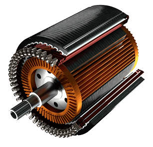
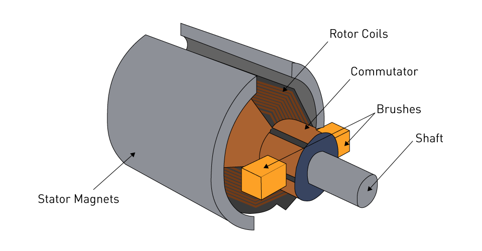
DC (or 'any current') motor
The DC motor represents the oldest and simplest electric motor design. Its stator contains either permanent magnets or excitation winding, while the rotor houses the working winding. The rotor winding connects to a commutator — a set of mechanical contacts that slide against brushes to conduct current into the rotating rotor.
The commutator functions as a controlled rectifier, directing current flow in the rotor in the desired direction regardless of rotor position. While this makes DC motors simple to control, the commutator represents their primary weakness due to mechanical wear.
Control characteristics of DC motors are straightforward: motor current corresponds directly to shaft torque, while motor speed correlates with induced voltage.
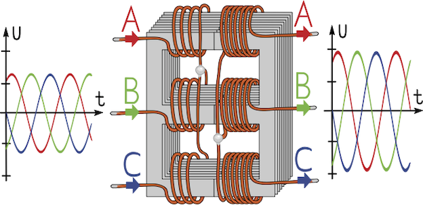
Other inductive loads
Due to our universal, modular architecture, the ESCx controller is well suited to drive other-than-motor inductive loads. For example, it is possible to drive a grid-attached three-phase transformer and make a two-quadrant power supply just with configuration. Please contact siliXcon for further information.