Phase current control
Controlability
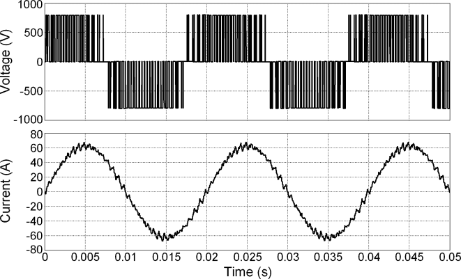
The controller uses PWM modulation (fast switching of the transistors in various configurations) to generate the desired current in the inductor. The following picture depicts the typical current waveform of a PWM-fed inductor:

For current control to work properly, certain system conditions must be met. Most importantly, the motor inductance plays a crucial role. The rate of current change is directly determined by the inductance and DC voltage according to the following equation:
If we substitute with the difference between link voltage and the actual back-EMF, and with the duration of 50 microseconds (representing one PWM cycle), we can infer that the saw wave amplitude of the inductor current during a single cycle may be high enough to overshoot the measurement range and trigger short circuit protection. In such a case, we consider the motor to be uncontrollable. The solution is either:
- to minimize the voltage difference (reduce control error with fine-tuning of the PID loops and the REST algorithm).
- to increase the switching frequency. Switching frequency is fixed for the ESCx families. Please contact us for custom solution.
- to increase inductance (motor redesign with different winding or magnetic material).
It's also important to note that motor inductance is not constant; it tends to decrease as current increases, particularly as the magnetic circuit approaches saturation. This is a common issue with, for example, outrunner motors that lack sufficient magnetic material and reach saturation quickly. In these cases, the motor may become uncontrollable above a certain current threshold.
- To check the dependency of inductance to the motor current, you can use the
identsatprocedure.
Another critical condition to consider is the impedance of the DC supply, typically a battery. For instance, if the DC resistance is significantly higher than the AC resistance, the control loop may encounter problems. This discrepancy can lead to higher current ripples, which may reduce the lifespan of the electrolytic capacitors and potentially induce hazardous states in the system. The mismatch between DC and AC impedance can compromise the stability and safety of the control system, making it essential to properly account for these characteristics in the design and implementation of the motor control system.
PID
The PID controllers are responsible for adjusting the voltages so that the target current is reached. In BLDC, only a single (scalar) current is treated, whereas in FOC, both torque (Q) and direct (D) axes are controlled separately.
- Hereby specified variables are located in the folder
/driver/pid_iqresp./driver/pid_id. - The PID is abbreviation of 'Proportional-Integral-Derivative' closed loop regulation.
- In the current control loop, only the P- and I- terms are used.
VECTOR
- Q axis: Torque-generating axis
- D axis: Flux-generating axis
BLDC
- BLDC algorithm uses only parameters from
pid_iq - Parameters from
pid_idare not used during motor control. It is presented only for the embedded identification procedures (identlin, identrun, ...). Therefore, changing its parameter will not affect motor control performance.
In BLDC we recommend to keep the P-coefficient at zero (default), since the loop is not designated to correct fast current fluctuations commonly present in block commutation.
Parameters
Parameters and settings for both pid_iq and pid_id can be set independently, but typically there is little reason to keep the axes dynamics different. Usually, the lower the motor inductance, the lower the P and I value should be, and vice versa. Those parameters can be auto-identified with identlin procedure (from ESCx 5.0).
| Parameter | Description |
|---|---|
P | Proportional term in the PID loop. |
I | Integral term in the PID loop. |
dcr (from ESCx 5.0)
This parameter defines the coupling between DC link voltage and PID output scaling. The higher the number, the more the input voltage fluctuation is compensated, but also the more the DC ripple current and potential oscillation is pronounced.
DTC
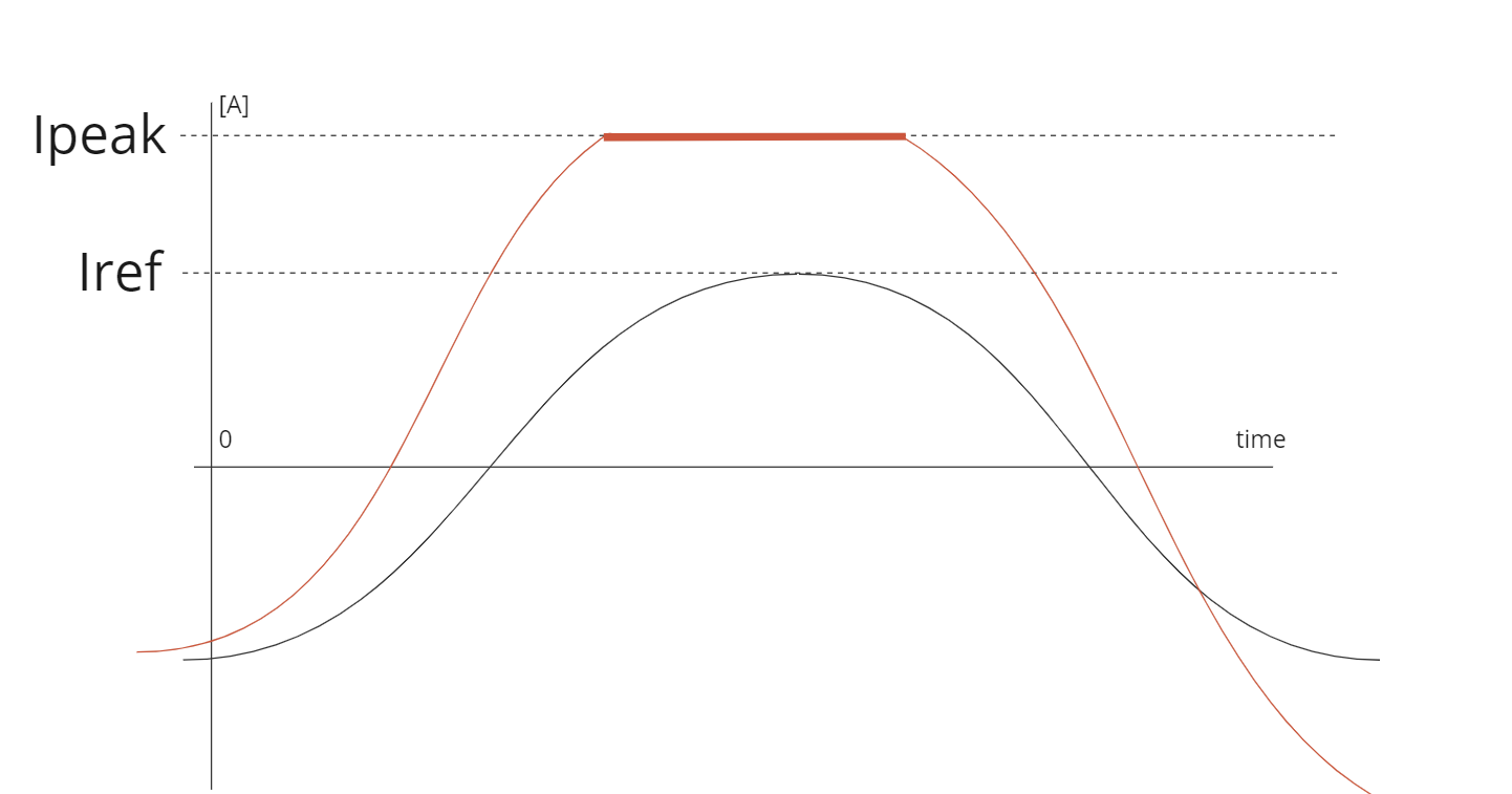
Sometimes, PID controllers may not react quickly enough to meet demanding performance requirements or handle emergency situations like short circuits. If the stator current reaches the current defined by ipeak at any time, even during an ongoing PWM cycle, the system automatically switches to Direct Torque Control (DTC). DTC offers way faster response times and better dynamic performance. This quick-acting alternative helps resolve issues like current overshoots rapidly and effectively prevents various hazardous outcomes in emergency situations. By combining these control methods, the system maintains efficient operation under normal conditions while having the capability to respond swiftly to unexpected challenges, enhancing both performance and safety.
The following picture illustrates the current waveform behavior respective to ipeak and iref under typical circumstances on a single motor phase:
