Motor sensor for BLDC
Sensor selection
This page covers motor sensor settings for BLDC. BLDC algorithm supports only sensorless mode and hall sensor.
- BLDC supports only HALL sensors or sensorless mode.
- The following variables are located in the
/driverfolder.
prest [-]
Preferred rotor position estimation mode.
| prest | name |
|---|---|
| -1 | Driver is deinitialized, powerstage is in HiZ |
| 0 | Auto mode |
| 1 | Force sensoreless mode. (hall sensors are disabled) |
| 2 | Force hall sensors. (Sensoreless is disabled) |
Auto-sensorless mode (prest = 0)
In this mode, the driver automatically selects between sensored and sensorless mode. Typically, hall sensors are used only for startup. If there is an error on hall sensors or they are disconnected, sensorless mode is used.
REST (Rotor position ESTimator) algorithm
Rotor position ESTimator (REST) is a module responsible for providing the reliable estimate of the rotor position from various sources for the BLDC (block commutation, 6-step drive). Generally, the REST can be configured as sensored or sensorless.
The following variables are located in the /driver/rest folder.
Wrong settings in this folder may cause unexpected motor spinning, even with in the stop command issued and/or any other freewheeling mode! Proceed with caution.
State variables
hall
Position of hall sensors. This variable is used only in the hall sensor mode.
| Value | Description |
|---|---|
| 0 | All hall sensors are off - Error value |
| 7 | All hall sensors are on - Error value |
| 1-6 | Hall sensor position |
Hall startup parameters
All the sensor parameters are automatically identified with the identrun procedure, no need to set it manually.
hinv [-]
UVW hall sensor polarity inversion.
A bitwise parameter that allows the user to flip polarity of the selected hall input. The inversion is useful e.g. with 60° hall sensor.
This picture depicts the schematic of two possible hall sensor configurations: 60° and 120°. With 60° configuration, the hall_W must be inverted:
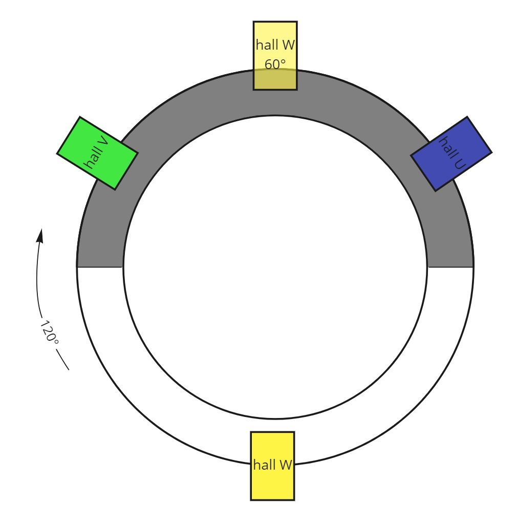
Colors of the hall sensors are usually used on MSENS wires.
This parameter is not automatically detected during identification procedure and must be set manually. For the most common variant with 120°, use the default, zero value.
hvar [-]
Hall sensor connection variant. This parameter maps the hall sensor inputs to the motor coils.
Sensorless startup parameters
maxp [pwm cycles]
PWM cycle = 50us
If a single commutation step takes longer than the time specified with this parameter, the BLDC will switch to "startup" mode.
smaxp [pwm cycles]
Sensorless startup maximal commutation period. During sensorless startup, if a single commutation step takes longer than the time specified with this parameter, one commutation step is forced (1/6 of electrical revolution).
The forced commutation time value is selected randomly, in range from 0 to smaxp to minimize the lock-up in a resonant peak. The default value yields to zero, which instruct the driver to use the value defined by maxp.
thr [LSB]
The threshold for detecting a zero-cross event during sensorless mode.
advancing [deg]
If parameter /driver/aac is non-zero, this parameter is ignored.
This parameter will force advancing angle to to the algorithm.