Motor sensor for VECTOR
Sensor selection
This page covers motor sensor types and their settings.
Hereby described variables are located in the folder /driver.
prest [-]
Preferred rotor position estimation mode.
| prest | name | Alternatives |
|---|---|---|
| -1 | Driver is deinitialized, powerstage is in HiZ | |
| 0 | Asynchronous mode | |
| 1 | Sensoreless mode | 128 - alternate mode (experimental) |
| 2 | Three Hall sensors | 66 - disable input holdoff filter |
| 3 | Sin-Cos sensor | |
| 4 | Resolver | |
| 5 | digital sensor, SSI 16-bit protocol | 21 - AS5048 mode; 149 - AS5048 mode with chip-select ; 37 - error detection override |
| 6 | digital sensor, BiSS protocol | 70 - skip CDS bit |
| 8 | digital sensor, 18-bit SSI32 for ZETTLEX sensors | |
| 10 | Incremental encoder | 26 - reference (Z) input; 58 - reference (Z) and PWM duty cycle homing input |
If the prest is changed the driver must be restarted or the reinit command must be run. Also, the command identrun must be run to identify the new sensor type.
- Un-identified sensor type may cause unexpected motor spinning, even with the stop command issued and/or any other freewheeling mode!
- The controller hardware never supports all the sensors listed in the table. Please check the hardware documentation for the supported sensor types.
- The firmware may not support all the sensors. As a reason, there are more firmware variants and you need to choose the correct one. Check you application documentation and the "Firmware Mods" section.
For motor with permanent magnets, you must use a sensor with absolute position output. Incremental encoders (AB, ABZ) are meant for asynchronous motors.
REST (Rotor position ESTimator) algorithm
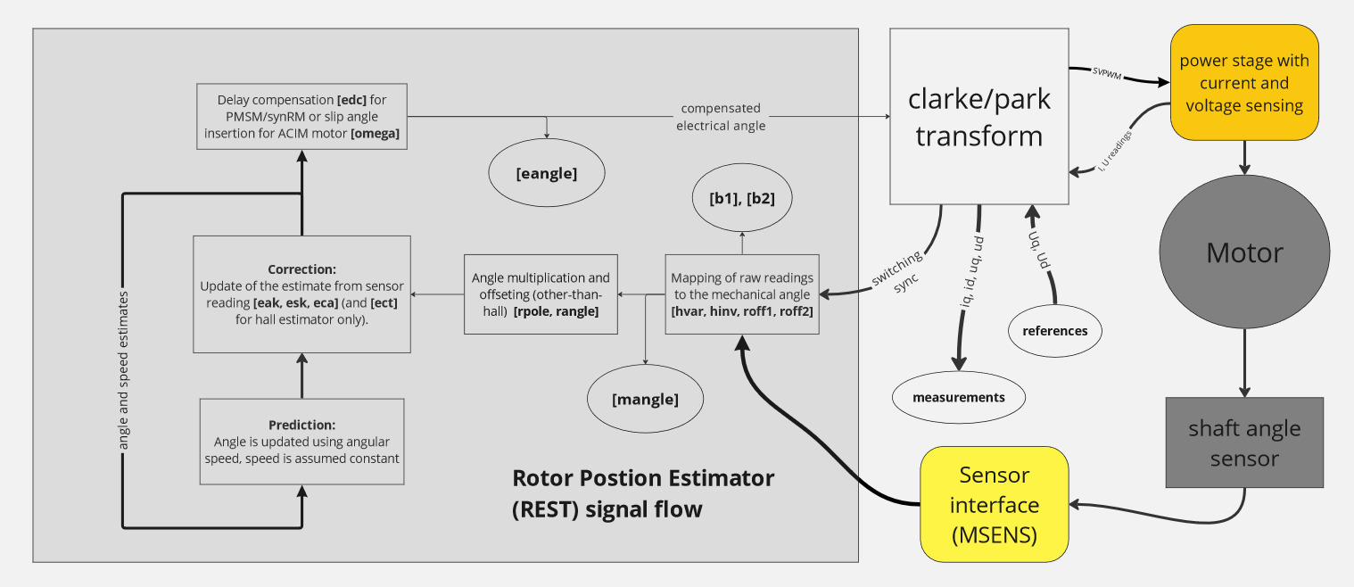
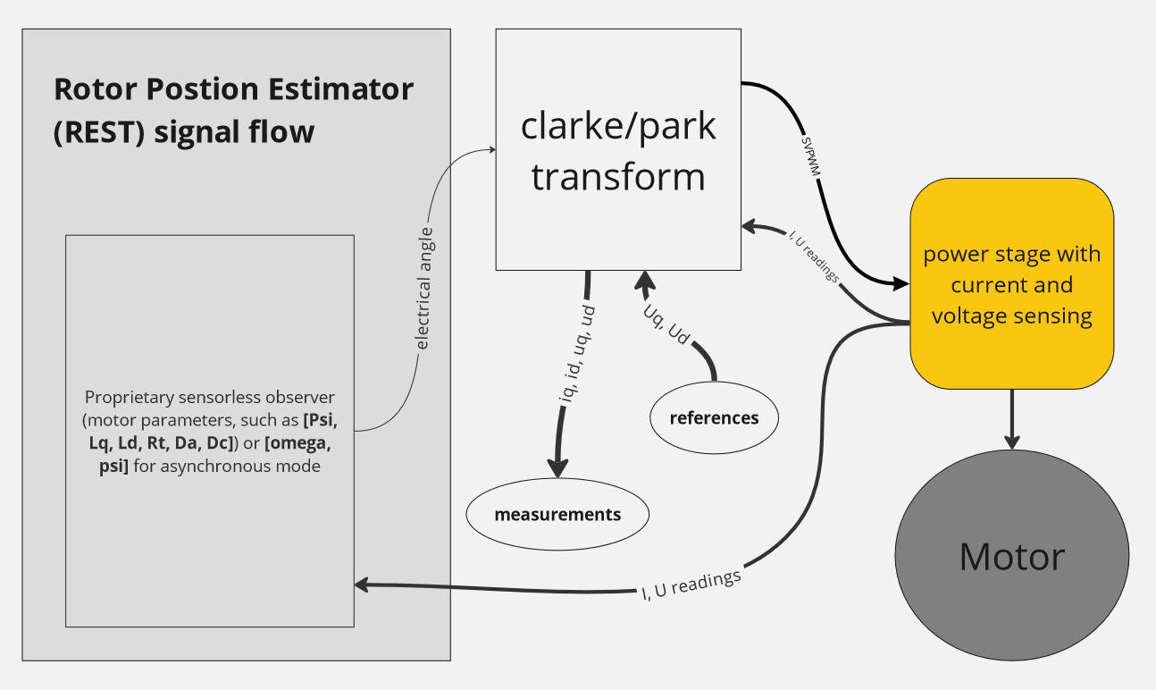
Rotor position ESTimator (REST) is a module responsible for providing the reliable estimate of the rotor position from various sources for the vector drive (FOC). Generally, the REST can be configured as sensored or sensorless.
Signal diagram of sensored mode
Signal diagram of sensorless mode
Hereby described variables are located in the folder /driver/rest.
Wrong settings in this folder may cause unexpected motor spining, even with in the stop command issued and/or any other freewheeling mode! Proceed with caution.
The VECTOR algorithm supports multiple motor sensors. Not all parameters are used for every sensor type.
State variables
eangle [rad]
Estimated electrical angle position output (after the processing).
mangle [rad]
Mechanical angle (intermediate state) after the sensor mapping (available only with certain sensor types).
b1 and b2
Mechanical angle represented in trigonometric coordinates (sin, cos) (intermediate state) after the sensor mapping (available only with certain sensor types).
hall
Mapped hall sensor reading. This variable is available only with the hall sensor mode.
| Value | Description |
|---|---|
| 0 | All hall sensors are off - Error value |
| 7 | All hall sensors are on - Error value |
| 1-6 | Hall sensor position |
Sensor mapping configuration
The sensor parameters may be automatically identified with the identrun procedure.
omega [erad/s]
If the PMSM (Permanent Magnet Synchronous Machine) motor is selected (by setting psi to other than zero), and asynchronous mode is selected (prest = 0),
this parameter defines the rotation speed of the forced magnetic filed (the electrical angle is not coupled to the shaft angle).
If the ACIM (AC induction machine) motor is selected (by setting psi to zero), this parameter defines either:
U/F ratio of the induction machine (when prest = 0 - sensorless), OR the current-dependent slip frequency of the induction machine (when prest is other than zero and a sensor is used).
hinv [-]
UVW hall sensor polarity inversion.
A bitwise parameter that allows the user to flip polarity of the selected hall input. The inversion is useful e.g. with 60° hall sensor.
This picture depicts the schematic of two possible hall sensor configurations: 60° and 120°. With 60° configuration, the hall_W must be inverted:
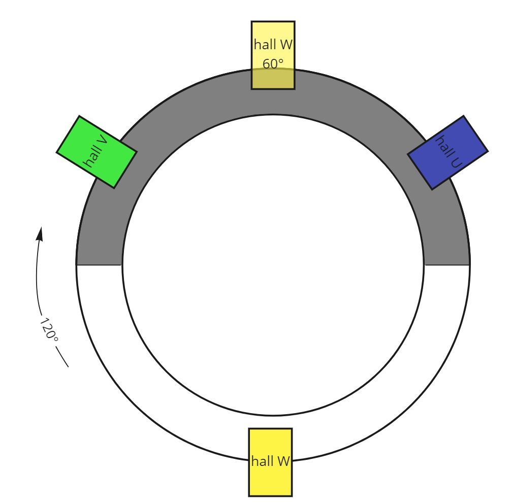
Colors of the hall sensors are usually used on MSENS wires.
This parameter is not automatically detected during identification procedure and must be set manually. For the most common variant with 120°, use the default, zero value.
hvar [-]
Hall sensor connection variant. This parameter maps the hall sensor inputs to the motor coils.
roff1 [LSB]
Rest Offset 1 (SIN) input offset.
roff2 [LSB]
Rest Offset 2 (COS) input offset.
rpole []
Rest Pole Defines the number of electrical revolutions per one sensor revolution.
rangle [rad]
Rest Angle Sensor-to-electrical angle offset
ppr [edges]
Pulses Per Revolution (total count of quadrature signal edges) per one sensor revolution. If PWM homing is used, sign of this parameter inverts the PWM duty cycle versus the slope of the quadrature signal.
This parameter is not automatically detected during identification procedure and must be set manually. For the most common variant with 120°, use the default, zero value.
Estimator configuration
The position estimator is a dynamic state observer that aims to filter out the sensor issues while preserving the zero phase shift and latency. Using this estimator, you can filter out misreadings or even compensate the intrinsic delay in the sensor hardware. Tuning up the estimator is an intensive topic and will be covered elsewhere.
esk [-]
The Estimator Speed Coefficient - the higher the number, the more the estimator 'trusts' the speed measured by the sensor. From ESCx 5.0 and above, this applies for sensorless mode as well.
eak [-]
The Estimator Angle Coefficient - the higher the number, the more the estimator 'trusts' the angle measured by the sensor. From ESCx 5.0 and above, this applies for sensorless mode as well.
eca [rad]
The Estimator Clip Angle used in the hall sensor mode only.
ect [s]
The Estimator Clip Time constant used in the hall sensor mode only.
edc [s]
The Estimator Delay Compensation can be used to compensate the time delay in the sensor hardware.
Automatic sensorless mode (fail-safe) configuration
Some sensors may have problems at high speeds. This parameter allows to automatically employ sensorless mode when the motor speed raises above the assh. The driver falls back into the sensored mode when motor speed is below the assl. If any of these parameters is set to zero, this function is disabled.
Most useful with bad hall sensors - hall sensors are used at low speeds, and sensorless mode is used at high speeds.
assl [RPM]
Auto SensorlesS Lo mode low threshold.
If motor speed /driver/rpmf is below this value, the selected sensored mode is activated (defined with the prest parameter).
assh [RPM]
Auto SensorlesS Hi mode high treshold.
If motor speed /driver/rpmf is abowe this value, sensorless mode is forced.