Testing the drive
This article describes how to test the motor, controller and power supply together. The testing purpose is:
- check the motor controllability (if / how well does the motor cooperate with the controller),
- check the power supply (battery) suitability for reaching the requested operating points,
- evaluate the performance and reach operating points: dynamic response, speed range, torque range, power range,
- evaluate the thermal performance of the system.
Before proceeding, we highly recommend gathering information about:
- Let's presume that the drive (motor, controller and power supply) is ready for a safe test. The motor is safely mounted on a test bench, the load is stable, and a sufficient, stable power is provided to the controller with a battery or a 2-quadrant PSU.
- Let's presume that a successful comlink with the device was already established (you have installed SWTools, the device is connected to your computer through one of its interfaces, connection options were set, etc.)
- Let's presume that you have configured the controller for the motor. Either you set all necessary parameters manually or identified them automatically.
- The motor will spin during the procedures! Please do all precautions to prevent any injuries!
- Never run these tests when the motor is mechanically connected to a ground-standing wheel!
VECTOR vs BLDC
Most of the drive modes are offered within both VECTOR and BLDC algorithms. Nevertheless, the VECTOR drive provides a richer set of measured values, as well as some extended control modes.
VECTOR drive algorithm is also generally sensitive to correct motor parameters, mostly when more advanced strategies are requested (sensorless control, flux control, ...)
Although most of our controllers have USB port, and it's the easiest way for accessing the system, USB is not an interference resilient interface. For power testing, we strongly recommend using CAN bus (e.g. through Peak CAN, Kvaser, ...)
Using the 'sili' tools
- Make sure that the motor is mounted safely on the test bench.
- Make sure that the motor phases and rotor position sensor (if selected) are connected properly to the controller.
- Connect a battery (or a 2-quadrant PSU) and turn on the controller (according to it's powering variant).
- Open the siliWatch tool according to its manual if you want to monitor the drive.
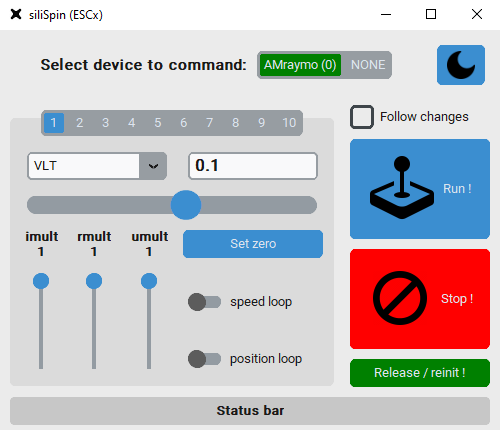
- Open the siliSpin tool according to its manual.
- Choose the drive mode in siliSpin, put in your command and click on Run!. The motor should start spinning.
- Check Follow changes to make the motor to react on your commands immediately.
- You may adjust the parameters through siliTune, emGUI or term during the active control and immediately see the changes.
- Click on Stop!. The motor should start freewheeling.

The siliSpin tool is written in Python and uses SXapi to access the device. You can write your own tool to access the device from Python or from a web browser environment.
Using the auxiliary commands
- Make sure that the motor is mounted safely on the test bench.
- Make sure that the motor phases and rotor position sensor (if selected) are connected properly to the controller.
- Connect a battery (or a 2-quadrant PSU) and turn on the controller (according to it's powering variant).
- Execute the
runcommand. The motor should start spinning - You may adjust the parameters through siliTune, emGUI or term during the active control and immediately see the changes.
- Execute the
stopcommand. The motor should start freewheeling.
- Those steps can be done with
emGUI, withtermor with a script. - To learn about commands for changing parameters, saving parameters, etc. in terminal, please check YOS commands documentation.
Using the VDS evaluation tool
- Make sure that the motor is mounted safely on the test bench.
- Make sure that the motor phases and rotor position sensor (if selected) are connected properly to the controller.
- Connect a battery (or a 2-quadrant PSU).
- Connect the VDS evaluation tool to your controller.
- Follow the tool manual

The VDS evaluation tool uses the ESCx CAN API. You can integrate our API to your CAN device to issue drive commands.
Automating the test
There are many ways how to automate your testing:
- using the ESCx CAN API to issue commands over CAN,
- using the SXapi to access the device either from Python or your web browser,
- using the end-of-line scripting to control the device from your system's native environment,
- using the on-board scripting to execute the testing script directly in the controller.
A test script example: sequence generation
Deploying a script to the controller is the easiest and most straightforward way. Let's say, we wish to generate a sequence, where the drive command from -50% to +50% of the voltage every second. Use the following content:
@c # Clear a running script (if any).
@w # Wait for the YOS/Shell to become responsive. Note that you may specify a timeout here.
@! # Do automatic log-in.

{
    run +0.5
    delay 1000
    run -0.5
    delay 1000
    branch s
}

stop
- save it into a file named e.g.
my_test.ys(theysextension will associate the file with thetermtool), - to execute, double-click the file. The terminal window will open and motor will start executing the sequence,
- you may use
emGUI,siliWatchto monitor the controller while the sequence execution, - press
ctrl+cwitin the terminal window to interrupt the script and stop the motor.
- Using the methods mentioned above, it is possible to design whole motor testing framework, multi-controller test-bench setups and more. Please contact siliXcon for assistance.
- For more information about scripting with the
termtool, check this tutorial.