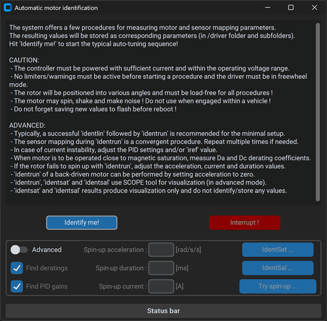
Automatic motor identification
This article describes how to perform identification of motor parameters by the controller, so that you do not need to enter them manually. In most cases of a PMSM motor, the automatic identification procedure results are good enough for a successful drive and a good for hands-on start. Winding resistance & inductances can be measured with identlin procedure (as well as inductance deratings and PI coefficients (from ESCx 5.0)), and the motor constant and sensor mapping using identrun procedure. The process will be described in this article.
Before proceeding, we highly recommend gathering information about:
- Hereby described procedure works only with PMSM motors. Check more about Motor types
- Let's presume that a successful comlink with the device was already established (you have installed SWTools, the device is connected to your computer through one of its interfaces, connection options were set, etc.)
- The motor will spin during the procedures! Please do all precautions to prevent any injuries!
- Never run these procedures when the motor is mechanically connected to a ground-standing wheel!
VECTOR vs BLDC
Identification of motor parameters for BLDC is same as for VECTOR, with these considerations:
prestvalues are different for BLDC. BLDC supports hall sensors only.- VECTOR drive is generally more sensitive to correct motor parameters, mostly when more advanced strategies are requested (sensorless control, MTPA, ...). You may skip
identlinfor set-ups that do not require these. - BLDC drive does not fundamentally require the results measured by
identlinandidenrunis used to determine the sensor alignment only.
Guided process
- Make sure that the motor shaft is unloaded, and the motor is mounted safely on a test bench.
- Make sure that the motor phases and rotor position sensor (if selected) are connected properly to the controller.
- Connect a battery (or a 2-quadrant PSU) and turn on the controller (according to it's powering variant).
- Open the siliTune tool according to its manual.
- Fill-in the form:
- Select your motor sensor type: choose in
init asdropdown menu. Wait for the confirmation message box. - Set appropriate phase current for your motor:
irefbox. - Set the motor pole pair count of your motor:
ppbox. This is required for correct speed/odo measurements only.
- Select your motor sensor type: choose in
- Click on Automatic identification button and follow the guidelines there.
- Evaluate the motor drive and if satisfied, save the parameters using the button in siliTune.

Manual process
- Make sure that the motor shaft is unloaded, and the motor is mounted safely on a test bench.
- Make sure that the motor phases and rotor position sensor (if selected) are connected properly to the controller.
- Connect a battery (or a 2-quadrant PSU) and turn on the controller (according to it's powering variant).
- Open a tool of your preference, either the term, or the emgui.
- If you want to visualize the result, open the scope, e.g. by pressing
ctrl+swhen in the tool window. - Select motor sensor type : execute
reinit(prest) whereprestvalue can be found here for VECTOR and BLDC. - Set appropriate phase current
/driver/irefaccording to your motor's specification. - Set the motor pole pair count in
/driver/motor/pp. This is required for correct speed/odo measurements only. - Execute the
stopcommand (if the motor is being driven). - If
/driver/limitis not 0, disable temporarily all the limiters. - Execute the
identlincommand. The motor will be positioned into different angles and the controller will find (motor resistance, inductances and PI coefficients). - Execute the
identruncommand. The motor will spin and controller will measure (motor constantpsiand sensor mapping parameters). - For sin/cos sensor, repeat
identrunat least 3 times to ensure convergence. - Evaluate the motor drive and if satisfied, save the parameters, e.g. using
savecommand.
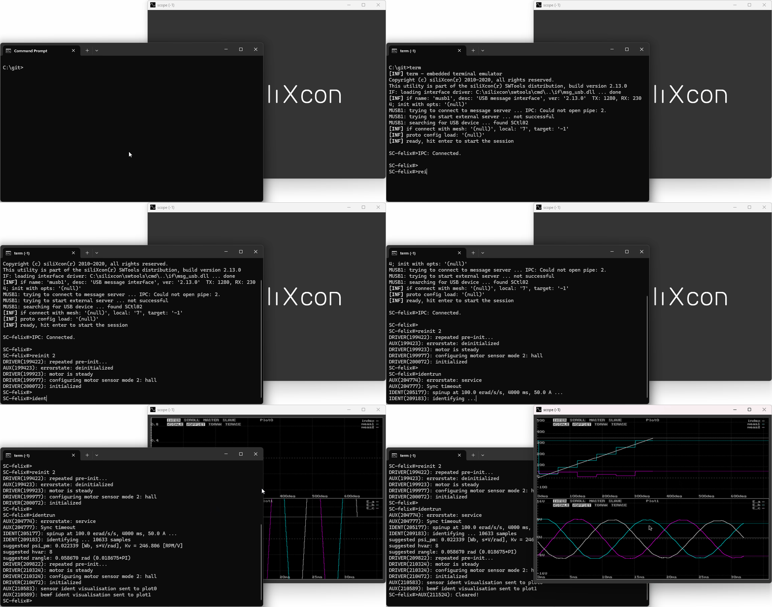
An example of the successful hall sensor identification (identrun-only) with term and scope:

The most common sensor types are:
| prest | name |
|---|---|
| 1 | Sensoreless mode |
| 2 | Three Hall sensors |
| 3 | Sin-Cos sensor |
| 4 | Resolver |
Identification with shaft load
Generally, an unloaded motor is preferred. However, in some cases, it is impossible (or impractical) to disconnect the mechanical load. In such cases, we offer a way of identification when the motor is back-driven. Process is similar as described above, with this exception:
- Make sure that the load comprises inertia only, e.g. shaft can still be positioned into various angles by
identlin. If the shaft can not rotate at all, theidentlinmeasurements will be wrong. - Before executing
identrun, spin the motor externally. - Execute
identrun 0(the '0' will disable the spin-up). - Wait at least 2 seconds and press Enter (to confirm the measurement).
- Stop spinning the motor (optionally). If you see "could not identify flux linkage", try again, possibly with higher speed.
Please be aware that identifying the parameters is not guaranteed to work under all circumstances and for all motors, batteries and other settings. The measured values (such as inductances, resistances) are only suggestions. They should be further validated against the motor specifications and evaluated properly.
Further adjustments and advanced tuning
Automatic identification may or may not be sufficient for reaching your target operating points with the motor. If you experience problems with motor controllability, it is possible to adjust (or enter) the parameters by hand. Please contact siliXcon for assistance.
Aside from automatic identification results, there are three modules that are the most usual subjects for further adjustments:
Automating the process
You can use scripts for identification. This is mostly provided as an example for the End-of-Line scripting which can be integrated into your vehicle's production line.
Script location is usually:
c:\silixcon\scripts\First_run\
This script will guide you through the steps.
- Run script
Motor_sensor_selection - Select motor sensor and confirm Enter
- Run script
Motor_identification - Read warning
- Press Enter and motor will be automatically identified
- In series production, if the same motor is used and the alignment between the phases and rotor sensor is fixed, there is no need to repeat identification for each unit. Parameters can be simply copied through a configuration file from one controller to another.
- After successful integration, before the volume production starts, the usual practice is that we embed your parameters directly into the custom application (so you do not need to care about configuration files).
- The identification trigger can be also implemented in-application upon request (e.g. when the user presses a special button combination on the vehicle).
- Another option is to deploy so-called container, which binds hardware, firmware and configuration into one, maintained entity. This is a preferred solution for the life cycle management of your vehicle and helps the homologation processes.