ASC - Analog Signal Conditioner
Description
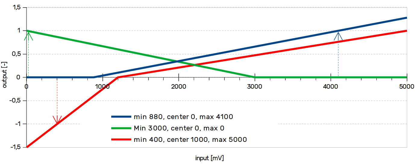
This block converts a fixed-point, discrete signal from analog-to-digital conversion into a normalized command. The block has several parameters that can be set to form the output curve. The ASC is suited for setting the analog sensor (e.g. throttle, brake lever). Transfer characteristic is shown in the picture below, with several different configurations of parameters min, center, max, and direction.
Settings
Parameter min should be set to the value of voltage which is on output on a sensor when is it fully released. Parameter max should be set to the value of voltage which is on output on a sensor when is it fully open. Ideally, the output of the ASC block should be a value from 0-1 (-1 to 1) according to a fully closed and opened analog sensor. In case absmin or absmax are not set, there is no constrain on ASC block output.
The center parameter is a special feature if is set to a non-zero value, the output of the ASC block is bi-directional (suitable for joystick control, or throttle release braking).
In case, when the sensor has the opposite direction of the output (low voltage – max output level), set parameter min to high voltage and parameter max to min voltage, the example is the green line below.
Transfer characteristic of the ASC block
Interactive transfer function
Safety settings
Absmin and absmax are parameters for the detection of malfunction on the input device. If the input value is under absmin or above absmax, output goes to NaN (Not a Number). This mostly results in motor disarm (depend on the application in the controller). This function can detect disconnected cable from the controller.
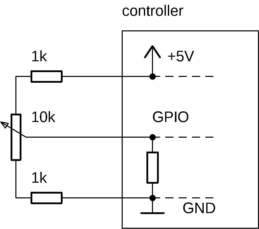
Safety example
In case of disconnection of any cable, GPIO value goes to the supply voltage or to GND. This malfunction results in NaN on the output of the ASC block.
ASC variables
| Parameter | Description |
|---|---|
min | Low threshold of the input range |
center | Center point of the input range. If this parameter is zero, the output is treated as unidirectional with a range from <0-1>. |
max | High threshold of the input range |
absmin | Input value under this threshold set output to NaN. * |
absmax | Input value above this threshold set output to NaN. * |
lpf | Output low-pass filter. More about lpf here. Negative value - distance filter |
*NaN typically do disarm, or permanently disable drive. This depends on application.
| State | Description |
|---|---|
in | Input signal to ASC block - usually [mV], value from GPIO input |
out | Output signal from ASC block. |
If you want to inver the input, switch min and max values.
Distance filter example
How to tune
Best approach to tune ASC is this:
- In term type
stopand press enter- With this, you override motor command and force it to freewheel
- Go to ASC folder
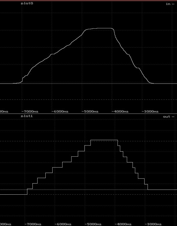
- Plot state
inandoutto scope into 2 plots - Move your input to low (potentiometer)
- Write value from
intominparameter - Move your input to high
- Write value from
intomax - Now move with your input a check the output in scope
After you finish, run command run. This will relese the override and you can ride. (Or restart the controller)