PWM Signal Conditioner
Description
This block converts any generic PWM (Pulse Width Modulation) input signal or servo PWM signal to a normalized command. In the case of generic PWM, limitation are:
- Duty cycle 0 or 1 are evaluated as no signal.
- The maximum width of pulse is 10 000 [us].
- The minimum width of pulse is 10 [us].
- To this corresponds requirements for the frequency to be in a range from 0.1 [kHz] to 10 [kHz].
Settings
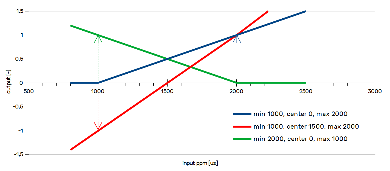
The block has several parameters that can be set to form the output curve. Transfer characteristic is shown in the picture below, with several different configurations of parameters min, center and max. The configuration is similar to the ASC block, but instead of analog voltage, the input is the width of the pulse.
Parameter min should be set to the value of voltage which is on output on a sensor when is it fully released. Parameter max should be set to the value of voltage which is on output on a sensor when is it fully open. Ideally, the output of the ASC block should be a value from 0-1 (-1 to 1). In case absmin or absmax are not set, there is no constrain on PWM block output.
The center parameter is a special feature, if is set to a non-zero value, the output of the PWM block is bi-directional (suitable for joystick control, or throttle release braking).
Transfer characteristic of the PWM block
Safety settings
Absmin and absmax are parameters for the detection of malfunction on the input device. If the input value is under absmin or above absmax, output goes to NaN (Not a Number). This mostly results in motor disarm (depend on the application in the controller). This function can detect disconnected cable from the controller.
If there is no pulse after timeout2, the output is set to NaN.
Parameter timeout1 is because of analog RC receivers. If there is no pulse after timeout1, PWM block will need 10 pulses to change input. This is when you lost RC signal, first pulses could be incorrect. These last parameters are always needed, because of safety. This results in requirements for the duty cycle (described above).
Variables
| Parameters | Description |
|---|---|
min | Low threshold of the input range |
center | Center point of the input range. If this parameter is zero, the output is treated as unidirectional with a range from <0-1>. |
max | High threshold of the input range |
absmin | Input value under this threshold set output to NaN. * |
absmax | Input value above this threshold set output to NaN. * |
timeout1 | No PWM for timeout1 need 10 pulses to change the output |
timeout2 | No PWM for timeout2 set output to NaN |
lpf | Output low-pass filter. More about lpf here. |
*NaN typically do disarm
| States | Description |
|---|---|
in | Input signal to PWM block. [us] |
out | Output signal from PWM block. [-1 - 1] |
If you want to inver the input, switch min and max values.