Communication stack
Supported communication interfaces
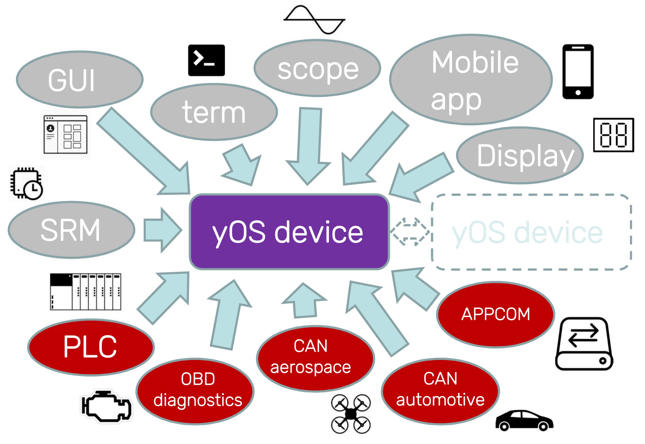
Each YOS device supports multiple communication interfaces, allowing to connect various peripherals, such as display, sensors, BMS or another controller. All of these interfaces can be also used for controller setting, state monitoring and firmware update over internet. Communication was designed specifically for hard real-time system needs, with minimal latency and perfect synchronization of multiple controllers in one system. Another focus is the pursuit of abstraction from the used physical layer. Commonly, we support these communication interfaces:
- SWD
- USB
- Bluetooth
- UDP/IP
- UART (up to 4x)
- CAN Bus (up to 2x)
- LIN Bus (up to 2x)
siliXcon network topology
The YOS communication stack is organized into a layered architecture designed to fully abstract the application from the underlying physical interface. Regardless of whether the device communicates over CAN bus, UART, USB, Bluetooth, or UDP/IP, the same protocol operates identically — only the physical and link layers adapt to the specific transport medium. This allows firmware and host tools to treat all interfaces uniformly.
The stack is split into three configurable layers:
| Layer | Purpose | Configured by |
|---|---|---|
| Physical layer | Bus speed, timing, and electrical parameters | msgconf (cfg0, cfg1) |
| Link layer | Datagram framing, addressing, and service identification composition | msgconf (cfg2, cfg3) |
| Protocol layer | Service protocol enable/disable and SID remapping | protoconf |
All layers are configured per-interface and stored in non-volatile memory (persistent across firmware updates).
The siliXcon protocol stack is the default topology. On request, a custom protocol can be implemented instead on a per-application basis (ModBus, ModBus/TCP, OBD/OBDII, CANOpen, CAN Aerospace, DeviceNET, DroneCAN, ...).
Protocol layer — service protocol
The system provides a proprietary service protocol to interact with the device. This protocol has been designed for low-latency, connection-less reliable data probing, configuring and upgrading in-application. It comprises a series of processes operating within the device, which are by default connected to all communication interfaces. The service protocol operates independently of the physical interface, allowing it to be connected to multiple communication interfaces at the same time. It does not depend on any item description files or object definitions — the device-specific data model is dynamically loaded from the device during runtime.
Service list
| Bit | SID | Service | Description | Used by |
|---|---|---|---|---|
| 0 | 0 | PWR (power) | Controls device power state (on/off/restart) and debugging output | term, emGUI, yosctl, bl_srm |
| 1 | 2 | FWD (forward) | Forwards messages between interfaces for indirect connectivity | msg_fwd interface driver |
| 2 | 4-5 | BL (bootloader) | Reads, erases, writes and configures firmware | bl_srm |
| 3 | 3 | ID (identification) | Transfers device metadata (HWID, SWID, UUID, ...) | auth, emGUI, yosctl, bl_srm |
| 4 | 6-7 | FS (filesystem) | Filesystem transfer | emGUI, yosctl |
| 5 | 8-9 | RPC (remote procedure call) | Executes commands in the device | emGUI, yosctl |
| 6 | 10-11 | STREAM (ASCII environment) | Standard input/output streaming | term |
| 7 | 20-22 | PLOT (scope) | Real-time data sampling and logging | scope |
The "Bit" column corresponds to the bit position in the protoconf enable/remap bitmask.
Service enabling and disabling
Each service can be independently enabled or disabled per interface using the protoconf command. A disabled service will neither transmit nor respond to incoming messages on that interface.
This allows restricting which protocols are reachable over a particular bus. For example, disabling the BL (bootloader) service on an external-facing interface prevents unauthorized firmware updates over that bus.
SID remapping
SID remapping requires YOS >= 2.8.5, BL (embl) >= 2.9.0, and SWTools >= 4.0.0.
By default, each service protocol uses a well-known SID (see table above). With SID remapping, a fixed offset is added to service SIDs on the configured interface. The offset is stored in bits 8-28 of the protoconf configuration word:
SID_offset = (conf >> 8) & 0x1FFFFF
This gives a 21-bit unsigned offset range (0 to 2,097,151).
A 2-bit remap scope field (bits 29-30) controls which services are affected by the offset:
| Scope | Remapped services |
|---|---|
| 0 | All services (PWR, FWD, BL, ID, FS, RPC, STREAM, PLOT) |
| 1 | BL, ID, FS, RPC, STREAM, PLOT |
| 2 | FS, RPC, STREAM, PLOT |
| 3 | STREAM, PLOT |
Services below the selected scope continue using their default SIDs. Setting scope to 0 (the default when bits 29-30 are unset) remaps every service — this is the most common configuration.
The effective SID for a remapped service becomes:
effective_SID = SID + SID_offset
On interfaces where SID maps to a bus identifier (e.g. CAN ID), the offset shifts all occupied identifiers accordingly. See CAN Bus — SID remapping effect on CAN ID for the full CAN ID formula.
SID remapping is useful for:
- Avoiding SID collisions when a device shares a bus with other non-siliXcon equipment
- Relocating service protocol CAN IDs away from application-specific message ranges
- Gateway setups where multiple protocol stacks coexist
The remap offset may also be used by application-level modules, such as the driver API protocol (process protocol), to relocate their own SIDs consistently with the rest of the stack.
When SID remapping is active on the device, a matching device configuration file must be provided to the host-side tools so they use the same relocated SIDs. See the protoconf command reference for configuration examples and the swtools.ini format.
Protocol layer — process (application) protocol
Process communication protocol is another set of running services in the YOS device. It is used for sending device's internal state variables (such as motor voltages, currents or control inputs) out via desired communication interfaces. It can be also used for setting parameters and sending commands for the process control during device normal operation. This feature is optional and can be turned on / off on request; in most firmware branches is turned off by default.
Process protocol is application specific. Nevertheless, siliXcon usually implements set of services that standardizes the following:
- Driver block : Driver internal states (such as voltages, currents or speed) can be sent out from YOS device. Parameters and commands can be issued.
- Common I/O block : states of control inputs and outputs (such as throttle, brake or buttons) can be sent out of YOS device. Parameters and commands can be issued.
The process communication protocol is described in detail in the corresponding utility/driver manual.
Physical layer
The physical layer determines bus speed, timing, and electrical characteristics for each interface. It is configured through the first two bytes (cfg0, cfg1) of the msgconf command. Each interface type defines its own interpretation of these bytes:
- CAN bus — see CAN Bus — Physical layer configuration
- UART — see UART — Physical layer configuration
Link layer
Every communication interface defines a link layer that encodes addressing and service identification into the interface-specific frame format. The msgconf command configures both the physical and link layers on a per-interface basis — cfg0/cfg1 control the physical layer, while cfg2/cfg3 control the link-layer datagram composition. A message is the basic communication block — all interfaces translate to a standardized format with the following segments:
- Sender address — identifies the originating device on the bus (for unicast and multicast)
- Receiver address — identifies the target device (for unicast and hidecast)
- Service ID (SID) — selects which service protocol handles the message
- Flags / message type
- Payload
Device address
Each device has its own address, managed by the setaddr command. This address is common for all communication interfaces — it is a logical, link-level address of device, not address of communication interface. By default, address of each device is set to 0. Change of address takes place after reboot.
Datagram types
The datagram type determines routing behavior:
| Datagram type | Sender address | Receiver address | Delivery |
|---|---|---|---|
| Broadcast | not included | not included | All devices, raw frame |
| Multicast | included | not included | All devices, decoded |
| Unicast | included | included | Single target device |
The physical encoding of these fields varies by interface. Physical and link-layer parameters are configured per-interface with the msgconf command.
CAN bus
On CAN bus, the CAN ID encodes both the sender address and the SID. The receiver address (for unicast) is carried in the first data byte. For the full CAN ID formula, SID remapping derivation, datagram types, and an interactive calculator, see CAN Bus — Link layer.
UART (UMSG)
On UART interfaces, the YOS communication system uses the UMSG protocol. Because UART is a point-to-point (1:n) connection, the sender address is implicit and not transmitted. For the full frame structure and implementation details, see UART — Link and transport layer.
Other interfaces
Link-layer datagram composition for other supported interfaces (USB, Bluetooth, UDP/IP, LIN, SWD) is not publicly documented yet. Please contact siliXcon for detailed protocol descriptions of these interfaces.