acs-rcbus RC bus adapter
The acs-rcbus connects the UART COM connector of a siliXcon controller to an RC receiver or a flight controller. The controller has a separate transmit (TX) and receive (RX) line. Most receivers with telemetry talk on one wire, some with inverted signals, and ExpressLRS receivers take only 3.3 V. The adapter does the matching: solder jumpers on its bottom side choose the circuit for your RC link.
The settings of the controller, the wiring and the setup of the receiver for every RC link are in the FALCON documentation: RC link.
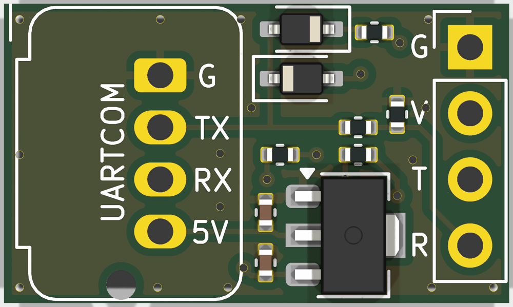
Top: J1 to the controller (left), J2 to the receiver (right).
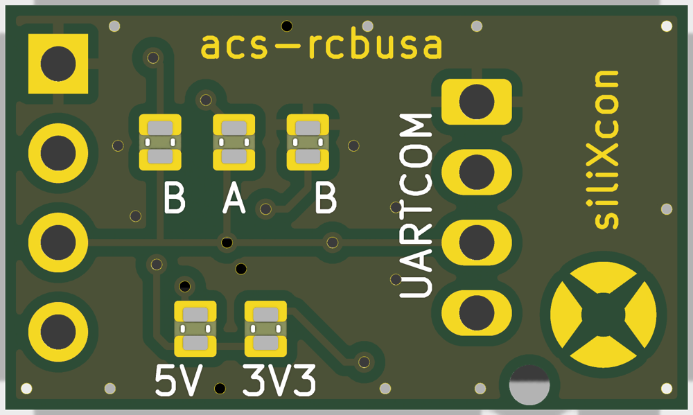
Bottom (the board turned over): the solder jumpers.
Specification
| Controllers | SC, SL, SX, AM, AX and TX, on the UART COM connector |
| Board | 19.4 × 11.5 mm, 1.2 mm thick |
| Supply | from COM+5V of the UART COM connector: 5 V, or 10 V on the AM (and on AX / TX ordered with 10 V); about 1.5 mA at most |
| Signals | controller side: TX and RX of the UART COM (5 V). Receiver side: 3.3 V pull-up on the bus line, 3.4 V on R |
| Receiver supply | none: the receiver has its own BEC or battery |
| Assembled | all parts on the top side; the receiver header J2 and the solder jumpers are left to you |
Power your receiver from its own BEC, not from the +5V output of the controller. Pin V of J2 is not connected.
Connectors
J1, to the controller
JST JWPF, 4 pins (B04B-JWPF-SK-R). It has the pinout of the UART COM connector of the SC and AM controllers, so the cable plugs straight in. For the other controllers, make a cable to their UART COM pins.
| Pin | Label | Signal |
|---|---|---|
| 1 | G | COMGND |
| 2 | TX | COMTXD, the controller transmits |
| 3 | RX | COMRXD, the controller receives |
| 4 | 5V | COM+5V, supplies the board (10 V on the AM) |
| Controller | COMGND | COMTXD | COMRXD | COM+5V | Pinout |
|---|---|---|---|---|---|
| SC | UART COM pin 1 (black) | pin 2 (white) | pin 3 (blue) | pin 4 (red) | SC I/O |
| AM | UART COM pin 1 (black) | pin 2 (white) | pin 3 (blue) | pin 4, 10 V (orange) | AM I/O |
| SX | 34 | 33 | 32 | 23 | SX I/O |
| SL | 10 (IOGND) | 27 (TXD) | 16 (RXD) | 35 (IO+5V) | SL I/O |
| AX, TX | 36 | 34 | 33 | 35 (5 V or 10 V) | AX I/O, TX I/O |
J2, to the receiver
Four 2.54 mm holes for a pin header (not fitted), labelled as seen from the receiver:
| Label | Signal |
|---|---|
| G | ground (COMGND) |
| V | not connected: the controller is not a BEC |
| T | the bus signal: from the receiver, to the controller RX |
| R | the controller TX, at 3.4 V, to the receiver RX (ExpressLRS / CRSF, KISS telemetry) |
A 3-pin servo plug (− + S) fits on G V T: − on G, S on T. Its + lands on V, which is not connected.
Solder jumpers
Five solder jumpers on the bottom side, labelled B A B and 5V 3V3. All are open from the factory. The setting
depends only on the RC link: the same on every controller.
| Solder | RC links |
|---|---|
| nothing | ExpressLRS / TBS Crossfire (CRSF), DShot with KISS telemetry |
A and 3V3 | Spektrum SRXL2, JETI EX Bus, JETI EX, Graupner HoTT, JR DMSS, FlySky iBUS sensor, bidirectional DShot |
B and B | Futaba S.BUS2, FrSky F.Port, FrSky S.Port |
Links that only send to the controller (S.BUS without telemetry, Graupner SUMD, JR XBus, FlySky iBUS, plain DShot) need no acs-rcbus: the cable goes straight to the controller.
Nothing soldered
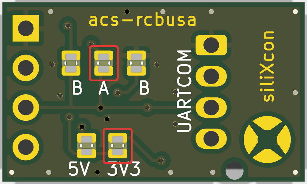
A and 3V3
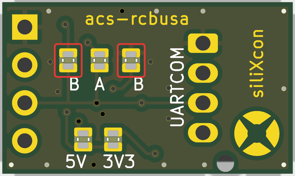
B and B
To close a jumper, bridge its two pads with a blob of solder. To open it again, remove the solder with desoldering wick.
Atogether withB: the controller would drive the line against the receiver.5V: no RC link uses it. Together with3V3it joins two supplies, and on a controller with 10 V on the COM connector (AM, and AX / TX ordered with 10 V) it puts 10 V on the line.
How it works
- One-wire bus, idle high (
Aand3V3): a Schottky diode joins the controller TX to the bus line. TX low pulls the line low; when TX is high the diode blocks, and a 2.2 kΩ pull-up to 3.3 V makes the high level. The receiver drives the same line, which goes to the controller RX. The pull-up also gives the fast edges that bidirectional DShot needs. - Inverted one-wire bus (
BandB): a second diode and a 1 kΩ resistor drive the line high (about 3.2 V) when TX is high, and 2.2 kΩ to ground holds it low when idle. - Full duplex (nothing soldered): the receiver TX goes straight to the controller RX (pin T). The controller TX reaches the receiver RX (pin R) through a 1 kΩ / 2.2 kΩ divider: 3.4 V, safe for 3.3 V ExpressLRS receivers. The divider is always fitted.
- 3.3 V: a small regulator (input up to 30 V) makes the 3.3 V for the pull-up from COM+5V, so the board works on 5 V and on 10 V UART COM connectors.
On a one-wire bus the controller also receives what it sends; the firmware removes this echo.
Without the acs-rcbus
For every RC link, the FALCON pages also show the circuit to build yourself from a diode and resistors, and the cable for the links that need no adapter: RC link.
Revisions
| Revision | Marking | Changes |
|---|---|---|
| a | acs-rcbusa (bottom side) | first release |