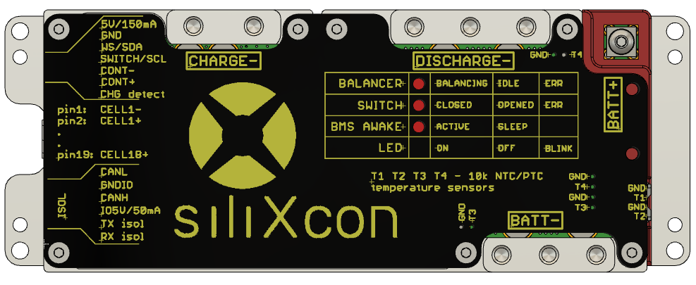
Pinouts
The signal connectors are Molex CLIK-Mate series
Connectors on the left side
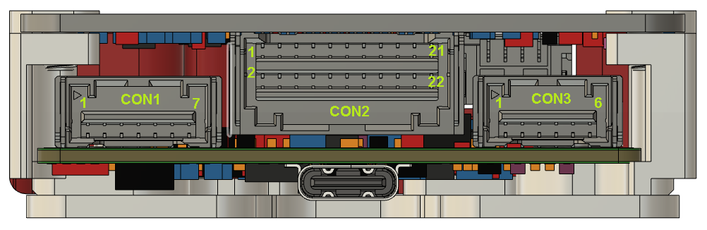
Con 1 - Accessories
- 5V-prot : supply voltage for display or LEDs
- GND-prot : ground for display or LEDs
- WS / SDA : data for LEDs / SDA pin of the display
- SWITCH / SCL : input from the button / SCL pin of the display
- CONT- : contactor switch output negative / KEY switch input negative
- CONT+ : contactor switch output positive / KEY switch input positive
- CHG DETECT : charger detection signal (active to BATTERY+ or to CONT+)
warning
These signals are not isolated from the BMS and battery.
Do not take the signals out of the battery pack.
- mating plug: 502578-0700
- crimp terminals: 502579-0100, 502579-0100
Con 2 - Balancing
1 . 0V : cell 1 minus
2 . cell1 + : cell 1 plus
3 . cell2 + : cell 2 plus
...
18 . cell17 + : cell 17 plus
19 . cell18 + : cell 18 plus
- mating plug: 503149-2200
- crimp terminals: 502579-0100, 502579-0100
Con 3 - Communication
- CANL : CAN Low
- GNDIO : isolated GND for external peripherals (CAN, UART)
- CANH : CAN High
- VCCIO : 5V power supply for external peripherals
- TX isol : UART communication
- RX isol : UART communication
info
- All these signals have a common ground - GNDIO.
- All the signals are isolated from the BMS
- mating plug: 502578-0600
- crimp terminals: 502579-0100, 502579-0100
Connectors on the right side
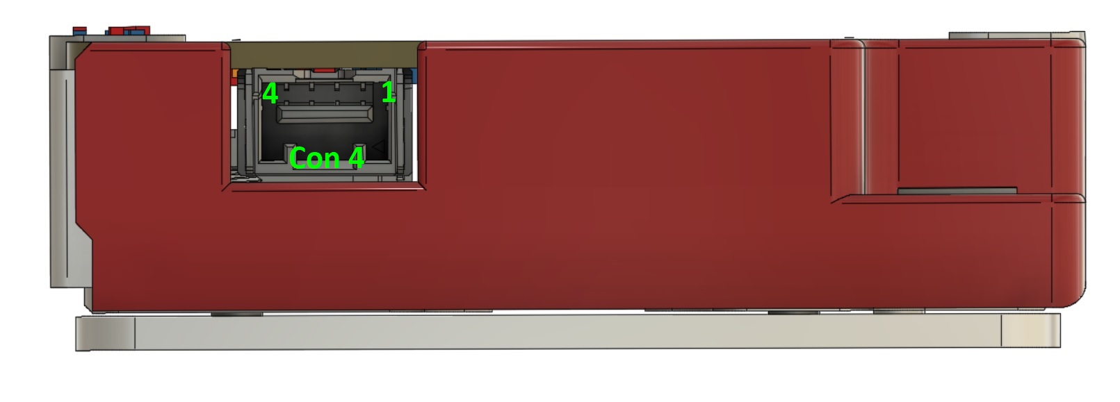
Con 4 - Temperature
- GND : temperature sensor GND
- T1_IN : temperature sensor 1 (NTC / PTC)
- GND : temperature sensor GND
- T2_IN : temperature sensor 2 (NTC / PTC)
warning
These sensors are not isolated from the BMS and battery.
- mating plug: 502578-0400
- crimp terminals: 502579-0100, 502579-0100
POWER connection
Battery:
- BATT+ : 1x M3 (TOP)
- BATT- : 6x M4 (TOP or SIDE)
Ports:
- DISCHARGE- : 6x M4 (TOP or SIDE)
- CHARGE- : 4x M4 (TOP or SIDE)
Status and error signaling
3 LEDs indicate basic status and BMS errors.
1. LED BALANCER
LED indicates balancer status
| LED | Status |
|---|---|
| OFF | Not balancing, no error |
| ON | Balancing |
| Blinking | Balancer error (/driver/balancer/error is not zero) |
2. LED SWITCH
LED indicates the status of the disconnector (transistors)
| LED | Status |
|---|---|
| OFF | Switch is OFF |
| ON | Switch is ON |
| Blinking | Switch error (/driver/error is not zero) |
3. LED BMS ACTIVE
LED indicates that BMS power supply is on - i.e. BMS is not sleeping.
| LED | Status |
|---|---|
| OFF | BMS is sleeping |
| ON | BMS is awake |
info
If BMS is sleeping, Switch and Balancer LEDs are OFF.