Motor sensors
AC electric motors are manufactured with various rotor position sensor types. The controller supports various interface types and paying attention to the matching selection is necessary.
- This common section covers the rotor position sensors only. For information about interfacing motor temperature sensor, please refer to the specific controller's electrical specification and guidelines.
- All siliXcon controllers feature sophisticated synchronous sampling technology for motor sensor signals. This technique substantially reduces electromagnetic interference concerns when routing sensor signals near power phase wires.
Supported rotor position sensors (according to their interface) are:
- Sensorless
- UVW Hall
- Sin-Cos
- Resolver
- Encoder
- Digital
No additional HW is necessary, the controller simply "computes" rotor position from the measured signals and motor parameters. The sensorless operation does not depend on the Motor sensor assembly variant.
BLDC driver algorithm does not require full motor identification for the sensorless operation.
| Pros | Cons |
|---|---|
| Simple and robust - no additional HW required. | Relies on motor parameters which can change with the temperature, age and other factors. |
| Precise at higher speeds. | Can have problems with operation at zero RPM under load. |
| Doesn't compromise the dynamic response. | The rotor position calculation loads the main processing unit. |
The signal is usually produced by three Hall sensors placed inside the motor in a 120° (rarely by 60°) span along with one electrical revolution. It can be also emulated by some advanced sensors, such as RLS AM4096. UVW commutation signal is composed of three digital signals. Each signal has two switchpoints per electrical revolution (the first switchpoint is from logical HIGH to log. LOW, second is from log. LOW to log. HIGH). Signals are shifted by 120° from each other (variants with signals shifted by 60° also exist). Examples of the signals are shown in the picture below.

When the UVW commutation signal is processed, it gives six discrete levels of rotor position for one electrical revolution. In the six switchpoints between the levels, the motor position is known with the least ambiguity. This information is enough when the BLDC motor driver algorithm is used. If the VECTOR control algorithm is used, these six switchpoints are not enough and positions between them have to be extrapolated. UVW commutation signal may not be the ideal choice (especially in applications where a high precision/motion control is required at low RPM) for the VECTOR driver algorithm since position estimation is needed.
Despite being traditionally viewed as a "low-end" solution for position sensing, Hall sensors offer compelling benefits that make them suitable even for high-end applications. Their inherent robustness and resilience to environmental factors, combined with our advanced interpolator algorithm, provide a reliable and cost-effective position sensing solution worthy of consideration across the entire application spectrum where the startup ripple is not a concern.
Rotor position measurement using the UVW commutation signal is shown in the picture below.

UVW hall sensors are supported by "a" or "h" Motor sensor assembly variant.
| Pros | Cons |
|---|---|
| Sense electrical (not mechanical) revolutions. No angle multiplication error occurs – it is suitable for motors with higher number of pole pairs. | Interpolation is needed if used with the VECTOR control algorithm. |
| Low-frequency digital signal – good immunity against electrical interference. | Max 13% ripple of generated torque at high dynamic operation. |
| Cheap, reliable and robust solution. | Max 13% to 50% torque ripple during stall or very low-speed operation. |
Selection guidelines
When considering integrated solutions that emulate UVW Hall sensor output, be aware that these usually implement internal angle multiplication, which can amplify potential angle errors. This negates the intrinsic benefits of Hall sensors. For in-shaft magnet implementations, we recommend using sin-cos or digital interfaces instead.
Example parts
For discrete Hall switches, select sensors that exhibit symmetrical behavior around field direction change. Namely look for high sensitivity, latching functionality (hysteresis) and bipolar sensing. Recommended sensor examples:
- Infineon TLE4946-2L
- Infineon TLI4961-1
Installation Best Practices
To ensure reliable operation, particularly during short-term motor current overload conditions, protect Hall sensors from coil induction interference:
- Add decoupling capacitor to the suply voltage close to the sensors themselves
- When using rotor magnets directly, position sensors between stator slots, not inside them, to minimize induction coupling
- For maximum resilience, use an external magnet ring with matching pole pair count to completely isolate sensors from motor coil interference
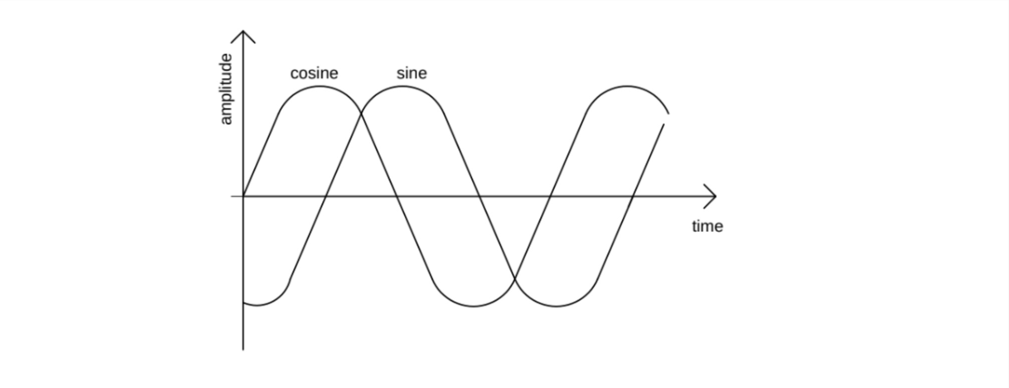
Analog sin-cos interface sensors offer versatile position sensing across various technologies (magnetic, optical, or inductive). Sin-Cos signal is composed of two analog signals of sinusoidal shape. Signals are phase-shifted by a quarter of the period and one period of sine (or cosine) signal corresponds to one mechanical turn of the motor (see pic. below). This type of signal is usually produced by a sensor consisting of a cylindrical permanent magnet glued to the rotor and a sensor chip located on the stator at a defined distance from the cylindrical magnet.

Sin-Cos motor sensor is supported by "a" Motor sensor assembly variant.
BLDC driver algorithm does not support Sin-Cos sensor
| Pros | Cons |
|---|---|
| Absolute and continuous position sensing. | Typically sense mechanical revolutions. Angle multiplication error could occur when using a motor with many pole pairs. |
| Suitable for position servo drives. | Analog interface – could be sensitive to electrical interference. |
| In the case of single-ended connection, offset calibration is required (can be done automatically by the controller). |
Selection guidelines
Based on our experience, the critical consideration when selecting these sensors is the matching of pole pair counts between the sensor and rotor. Many sin-cos sensors detect mechanical revolution rather than electrical angle, requiring the controller to perform angle multiplication for proper motor commutation. For sensors utilizing a single sensing element (such as in-shaft magnet designs), we've found that the practical multiplication limit is typically five times before accuracy degradation becomes problematic. Although a firmware compensation table reduces the symptoms, the inacurracies tend to drift with time (temperature, age, ...). This limitation should be carefully evaluated when selecting sin-cos sensors for applications with high pole pair counts to ensure reliable position feedback and optimal motor performance.
Example parts
When interfacing with sin-cos analog output sensors, output voltage range is the primary consideration. Optimal performance is achieved with sensors featuring ratiometric output centered at mid-supply voltage (2.5V when using the 5V provided by our controller). For signal integrity, the amplitude swing should remain within 90% of both upper and lower voltage margins, avoiding rail saturation that could introduce non-linearities. The following sensors with sin-cos output have been extensively tested and proven reliable in field applications:
Magnetic (in-shaft, in-axis magnet):
- RLS AM256 or AM4096 chip
- RLS RMB29 module (PCB)
- RLS RM44A module (mechanical assembly)
Inductive (can be off-axis, can match pole pair count):
- Renesas IPS2200 series (e.g. IPS2200BI1R, see IPS2200STKIT to evaluate)
Installation Best Practices
To maintain reliable sensor performance, especially during short-term motor current overload conditions, implement these protective measures against coil induction interference:
- Install decoupling capacitors on the supply voltage in close proximity to the sensors themselves.
- For in-shaft magnet sensors, ensure precise magnet alignment, as any mechanical misalignment or temperature instability will be amplified through angle multiplication, potentially introducing significant control errors.
- For maximum resilience, position magnets at sufficient distance from motor windings to minimize electromagnetic interference with the sensing elements.
Resolver is a motor angle sensor with one excitation winding and two sense (sine and cosine) windings, electrically perpendicular to each other. The resolver is fed by AC voltage of known amplitudes and frequency to the excitation winding. Voltage is measured on both sense windings (sine and cosine winding). The voltage across these sense windings has the same waveform as the voltage across the excitation winding. The amplitude of the sensed voltages is modulated by rotor position, as shown in the figure below. Resolver is a common rotor angle sensor in the industry, it is used in high-end drives and servos. Resolvers are usually constructed to sense mechanical revolutions (one period of the modulated sine or cosine voltage corresponds to one mechanical turn). Some resolvers have more pole pairs and can sense electrical revolutions.

Resolver motor sensor is supported by "r" Motor sensor assembly variant.
BLDC driver algorithm does not support Resolver sensor
| Pros | Cons |
|---|---|
| Absolute and continuous position sensing. | Typically sense mechanical revolutions. Angle multiplication error could occur when using a motor with many pole pairs. |
| Robust solution with no semiconductors or active electronics. | Analog interface – could be sensitive to electrical interference. |
| Suitable for position servo drives. | Higher weight, larger dimensions. |
| No offset in sense winding voltage – easy to set up the drive. | Higher price. |
SC, SL, AX and TX controller may need to attach a driver for the excitation coil to get a quality signal reading from the resolver. Please contact siliXcon for more info.
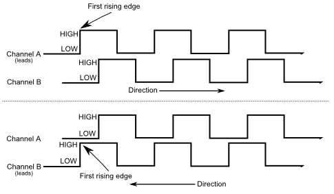
AB encoder signals represent one of the most fundamental position measurement methods. This approach utilizes two quadrature signals (A and B) with a 90-degree phase shift between them. This configuration enables the detection of both position increments and directional information. The primary limitation of AB encoders is their inability to provide absolute position information. The system inherently only tracks relative movement, requiring a separate homing procedure to establish absolute position reference for most motor control applications. One notable exception is AC Induction Motor (ACIM) control, which can operate effectively without absolute rotor position information, making AB encoders particularly suitable for these applications.
The suported interface types are:
- AB (no reference signal, suitable for ACIM motors)
- ABZ (with reference signal)
- AB+PWM (with PWM homing augmentation)

Encoder motor sensor is supported by "d" Motor sensor assembly variant.
BLDC driver algorithm does not support Encoder sensor
| Pros | Cons |
|---|---|
| Simple digital interface. | Needs homing (or augmentation) - doesn't fully define the motor angle. |
| Suitable for ACIM motor / lower end PMSM. | Higher-speed digital interface – could be sensitive to electrical interference (depending on the resolution). |
| Cheap. | May suffer from angle multiplication isssues (depending on the resolution). |
- Please contact siliXcon for more information and wiring diagrams.
- AM, AX and TX have limited support for encoder sensors.
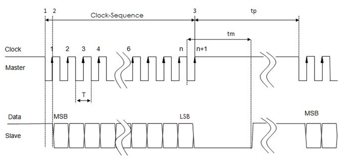
Sensors with digital interfaces completely offload angle measurement processing from the motor controller, allowing for more efficient resource allocation. These sensors can utilize various sensing principles, including induction, magnetic, or optical technologies. The critical factor for seamless integration is the digital interface itself. Our products support a comprehensive range of industry-standard protocols:
- SSI
- SSI32
- BiSS
- BiSS32

Digital motor sensor is supported by "d" Motor sensor assembly variant.
BLDC driver algorithm does not support Digital sensor
| Pros | Cons |
|---|---|
| Absolute and continuous position sensing. | Complex cirucitry in close proximity to the motor (may suffer from temperature shocks, humidity, vibrations, etc). |
| Suitable for position servo drive. | High-speed digital interface – could be sensitive to electrical interference. |
| Typically sense mechanical revolutions. Angle multiplication error could occur when using a motor with many pole pairs. | |
| Higher price. |
- Please contact siliXcon for more information and wiring diagrams.
- AM, AX and TX have limited support for digital sensors.