Product overview
AM controller
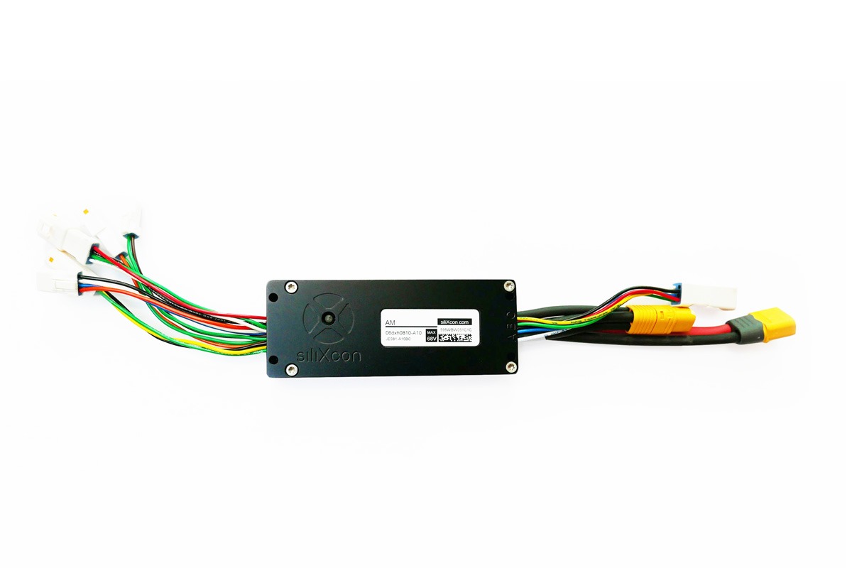
The AM is the lightest standard member of the ESC3 controller family. It can be used in a wide range of applications, especially in industrial and automotive. Using the most modern technologies, it achieves extreme dynamics and maximal efficiency. It implements smooth start and regenerative braking, all within minimum dimensions. The AM controller is capable of driving all common types of electric motors.
Controller editions (housing variants)
AM controller may come in different housing variants, called editions. Each edition provides different levels of protection and thermal management. The following editions of the AM controller exist:
- Standard edition. Aluminium enclosure, waterproof (sealed). Best protection and thermal conductivity.
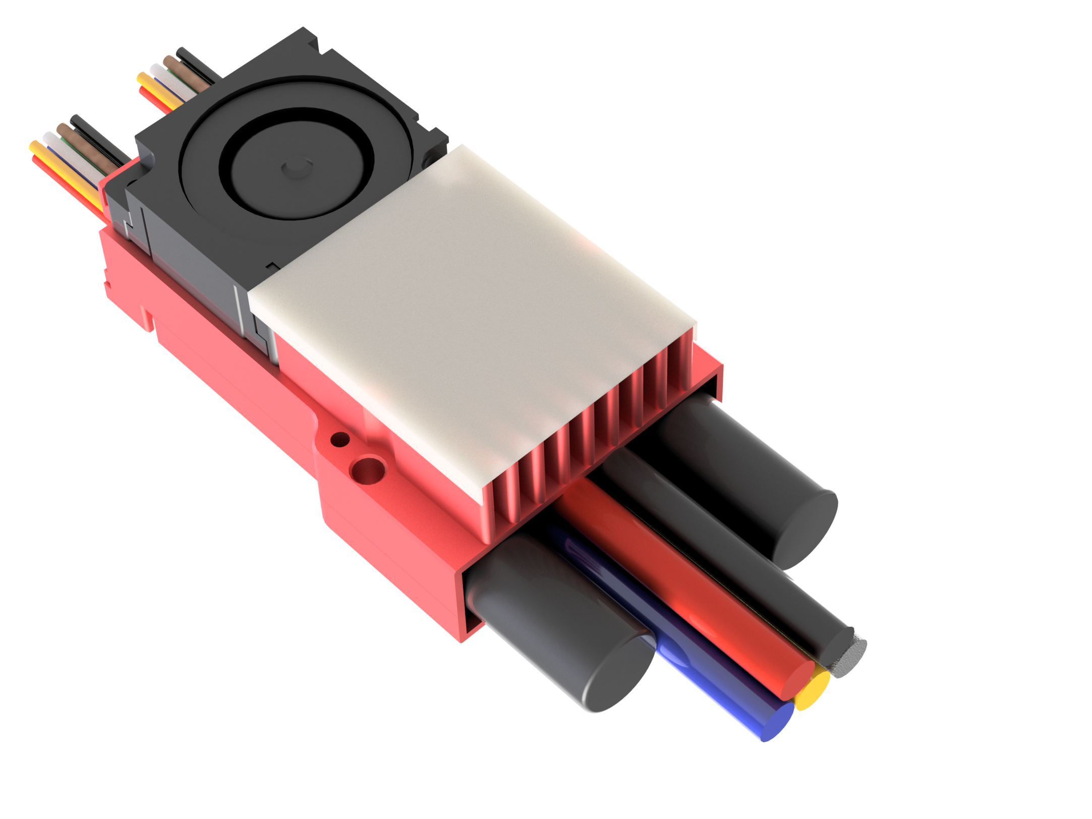
- Raptor Fan. Optimized for airborne applications with active air cooling.
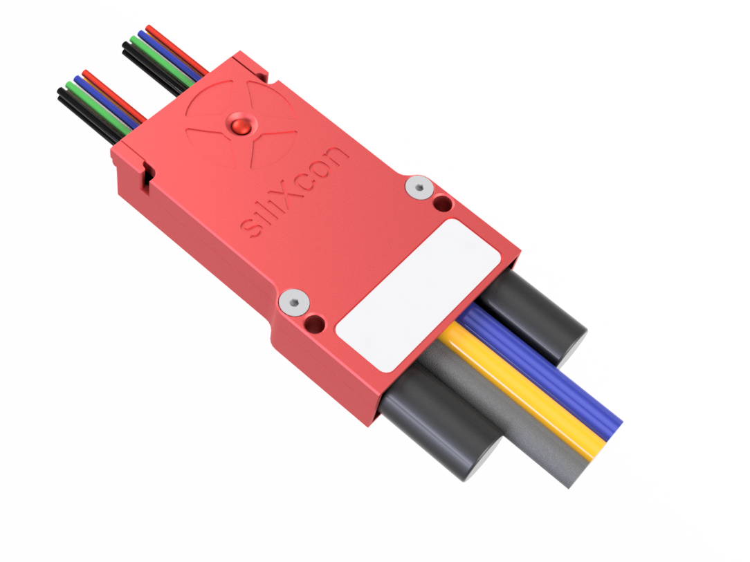
- Raptor Flat. Optimized for airborne applications.
- Standard edition
- Raptor Flat
- Raptor Fan
Applications
- Automotive or industrial motor control
- Electric hand tools and equipment
- Hi-end e-bikes, surf boards
- Combustion engine starter-generators
- Military inertial stabilization
- Professional drones, RC models
- Research and development
- Servo drives
Applications
- Professional UAV and multirotor drone propulsion
- Fixed-wing electric aircraft drives
- eVTOL and hybrid-electric air mobility platforms
- Military and defense autonomous aerial systems
- Reconnaissance, surveillance, and tactical drone missions
- High-altitude long-endurance (HALE) aircraft
- Aerospace actuator and servo control
- Counter-UAS and loitering munition powertrains
Product identification label
Each product is equipped with an identification label containing pertinent information.

| Position | Name |
|---|---|
| 1 | Maximum operating voltage |
| 2 | Country of manufacture |
| 3 | SN QR code |
| 4 | Serial number |
| 5 | Product Name |
| 6 | Order code |
Product variants
The AM controller is a very versatile product. To match all specific requirements, multiple properties can be adjusted, so many variants exist. Different variants are denoted by different MPN (Manufacturer Part Number).
The MPN consists of several parts:
- Base name -- denotes compatible firmwares (e.g. AM-felix, AM-raptor, AM-serpent)
- Assembly code -- defines voltage/current rating, communication interfaces, motor sensors, and internal HW configuration
- Finish variant -- defines signal/power wiring, housing, and enclosure

Base names and compatible firmwares
| Base name | Target application | Compatible firmware |
|---|---|---|
| AM-titan | All available applications, used with samples | LYNX, FALCON, OPHION, ECHO |
| AM-felix | Ground vehicles (e-bikes, motorbikes, scooters) | LYNX |
| AM-raptor | RC models (drones, planes, boats) | FALCON |
| AM-serpent | Industrial electric drives | OPHION |
Standard MPNs
Decode MPN
Features
- Assembly code
- Internal HW configuration
- Finish 1
- Finish 2
Standard variants
- AM-titan standard 1
- AM-raptor high performance
MPN: esc3-am2a_06dxh0810-800_JF3C1-A10BB
Equipped with LYNX firmware. Intended for small and light wheeled electric vehicles such as e-bikes or kick-scooters. Uses Amass XT60 and MT60 power connectors with JST JWPF signal connectors. Galvanic isolation is enabled.
| Parameter | Variant code | Description |
|---|---|---|
| Controller size | 06 | Six transistors in the power stage |
| Power features | d | No additional power features |
| Connectivity | x | USB, isolated CAN Bus, isolated UART (5 V logic levels) |
| Motor sensors | h | Three Hall sensors, sensorless control |
| Limit voltage | 08 | 80 V absolute maximum |
| Current range | 10 | 100 A measurement range of phase current (amplitude) |
| Internal HW config | 800 | Activation input for powering, galvanic isolation enabled |
| Signal connectors type | J | JST JWPF connectors |
| Present signal conns | F3C | USB, CAN, UART, Power, CNTRL1, MSENS, DIN1, DIN2 |
| Signal wires | 1 | 10 cm, AWG24, PVC insulation |
| Power connectors | A | Amass XT60 male (battery), MT60 female (motor) |
| Power wires | 1 | 4 mm2 (AWG11), SIFF, 10 cm battery / 6 cm motor |
| Housing | BB | Aluminium housing, waterproof, black elox |
MPN: esc3-am2a_08dsh0820-800_PC901-A10E1
Equipped with FALCON firmware. Intended for aircraft vehicles (drones, high-end RC models). It uses latest generations of the mosfets to deliver more current.
Built-in LED status indicator
The AM controller has a built-in LED which indicates the state of the control program:
- Bootloader -- LED lights very briefly while firmware version and checksums are checked. If the controller remains in this state for more than a few seconds, there is a firmware problem. Try updating the firmware.
- Main program -- LED is lit while the Driver initializes.
- Driver -- the motor control part of the firmware:
- LED off -- Driver successfully initialized, motor can be driven
- LED on solid -- Driver status word is non-zero, a high priority limiter may be active. LED turns off after 2 second timeout when condition passes.
- LED blinking -- an error occurred. LED blinks 16 times, pauses, then repeats. Each blink represents one bit of the error word (long blink = 1, short blink = 0, LSB first).
Accessories
Signal connector mating parts (JST JWPF)
| Connector | JST Part Number |
|---|---|
| USB mating connector (4-pin female) | 04R-JWPF-VSLE-S |
| Power mating connector (3-pin male) | 03T-JWPF-VSLE-S |
| UART COM, CNTRL1 mating connector (4-pin male) | 04T-JWPF-VSLE-S |
| CAN, PAS mating connector (3-pin female) | 03R-JWPF-VSLE-S |
| DIN mating connector (2-pin female) | 02R-JWPF-VSLE-S |
| DOUT mating connector (2-pin male) | 02T-JWPF-VSLE-S |
| Motor sensor mating connector (8-pin female) | 08R-JWPF-VSLE-D |
| Receptacle contact 22-26 AWG | SWPR-001T-P025 |
| Tab contact 22-26 AWG | SWPT-001T-P025 |
| Crimp tool | WC-JWPF |
| Removal tool | EJ-JWPF |
Power connectors
- Battery mating connector: Amass XT60H-F
- Motor mating connector: Amass MT60-M
Mounting screws
- 4x M3 screw. Recommended mounting torque: 1.3 Nm.
- Refer to the AM controller drawing.
Thermal grease
- To improve cooling of the controller, apply thermal grease to the mounting area. Example: Electrolube HTC, AG termopasty HPX