SC controller
The standard SC edition: a compact, lightweight 15 kW brushless motor controller in a sealed housing with flying signal wires and power terminals. Designed for low-performance e-motorbikes, scooters, go-karts, and lightweight electric vehicles where compact dimensions matter.
Applications
- Low-performance e-motorbikes and lightweight electric vehicles
- Electric scooters and personal mobility devices
- Industrial motor drives and pump control
- Electric go-karts and recreational vehicles
- Agricultural and horticultural electric equipment
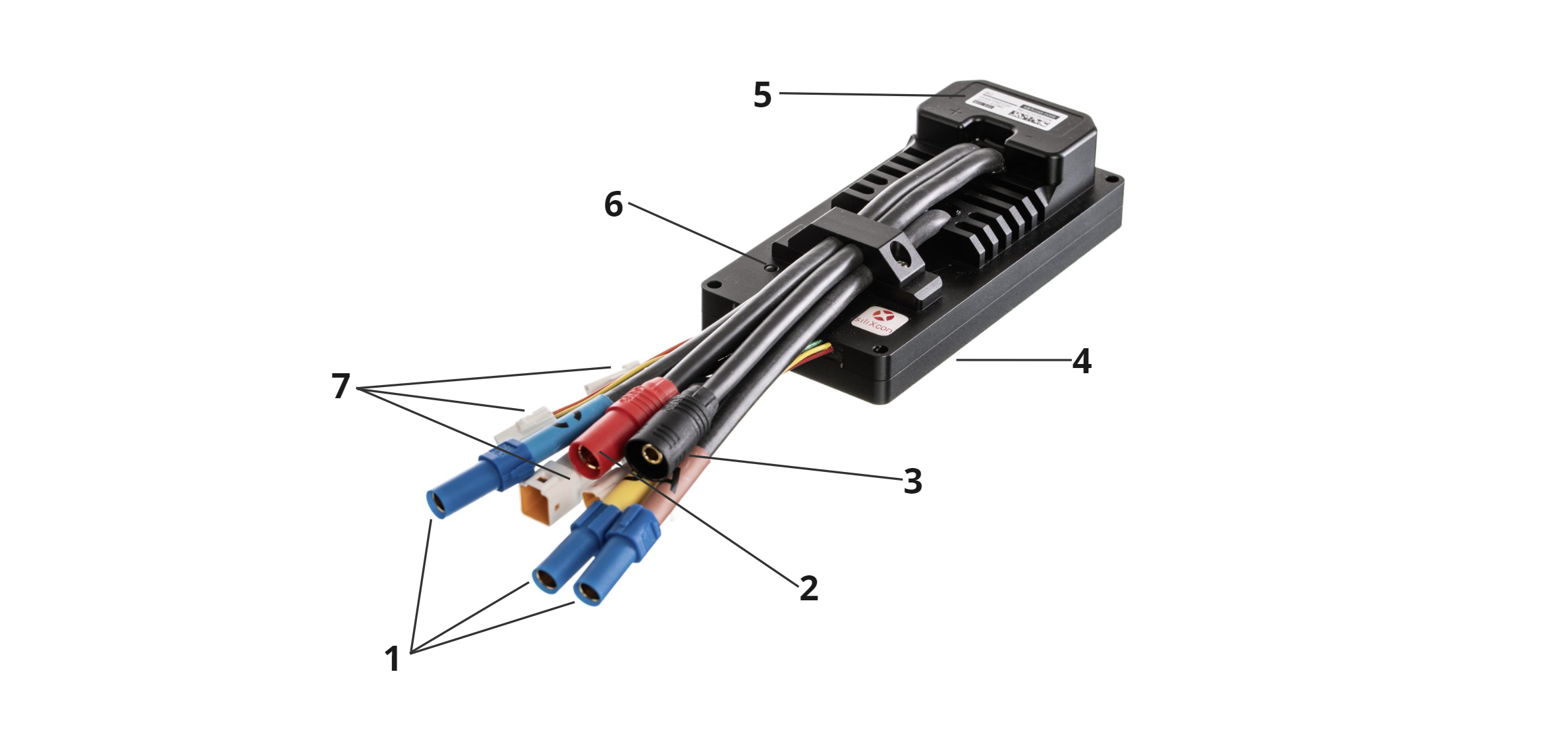
| Position | Name |
|---|---|
| 1 | Motor phase connector - XT150 |
| 2 | Battery + connector - AS150 |
| 3 | Battery - connector - AS150 |
| 4 | Mounting surface |
| 5 | Product label |
| 6 | Status LED |
| 7 | Signal connectors - JST JWPF |
Signal part is connected via several signal connectors - 7. Battery is connected by AS150 connector - 2, 3, XT150 connector is used for motor phases - 1. The controller should be installed by placing the mounting surface - 4 on a flat metal surface and securing it by four screws. Status LED - 6 indicates error states.
Product identification label
Each product is equipped with an identification label containing pertinent information.

| Position | Name |
|---|---|
| 1 | Maximum operating voltage |
| 2 | Country of manufacture |
| 3 | SN QR code |
| 4 | Serial number |
| 5 | Product Name |
| 6 | Order code |
LED status indicator
The LED status indicator informs about the current state of the motor controller according to table below.
| LED state | Controller condition |
|---|---|
| Permanently turned OFF | Controller is not powered up |
| Briefly turned ON and after a few sec OFF | Controller is powered and fully functional |
| Permanently turned ON | Controller indicates that any of the protections are active. Output current can be limited. |
| Blinking | Controller indicates an internal error and is blinking a 16-bit error code. Controller's power stage is deactivated |
Accessories
Signal connector
- DOUT mating connector: JST 02T-JWPF-VSLE-S
- DIN mating connector: JST 02R-JWPF-VSLE-S
- Motor sensor mating connector: JST 08R-JWPF-VSLE-D
- Control I/O 2 mating connector: JST 08T-JWPF-VSLE-D
- Control I/O 1, UART mating connector: JST 04T-JWPF-VSLE-S
- Power mating connector: JST 03T-JWPF-VSLE-S
- CAN mating connector: JST 03R-JWPF-VSLE-S
- USB mating connector: JST 04R-JWPF-VSLE-S
- Receptacle contact 22-26 AWG SWPR-001T-P025
- Tab contact 22-26 AWG SWPT-001T-P025
- Receptacle contact 22-26 AWG, crimped 0.2m wire SWPR-22LK200-D
- Tab contact 22-26 AWG, crimped 0.2m wire SWPT-22LK200-D
- Crimp tool WC-JWPF
- Removal tool EJ-JWPF
Power connectors
- Motor phase mating connector: Amass XT150-Main
- Battery+ mating connector: Amass AS150-M Red
- Battery- mating connector: Amass AS150-F Black
Set of mating connectors
siliXcon can provide a set of mating connectors for end-application prototyping. The signal JST connectors for the default variant (USB, CAN, UART10V, POWER, CNTRL1, CNTRL2, MSENS, DOUT) are precrimped with 10cm cables. Mating motor phases and battery connectors are included without wires. Please contact siliXcon customer support for more details.
Mounting screws
- 4x M4 or M5 screw. M4 screws are through the heatsink, M5 screws have a thread in the heatsink. Refer to the SC controller drawing.
- for through-hole mounting, minimum thread depth is 1.5 x screw diameter. Tightening torque depends on the material of the mounting base.
Thermal grease
- to improve cooling of the controller, you should apply thermal grease to the mounting area of the controller. Example: Electrolube HTC, AG termopasty HPX