Product overview
SC controller
siliXcon 15 kW brushless motor controller
is a very compact and lightweight controller featuring flying wires for signals and power terminals. Its innovative thermal management allows it to minimize dimensions and weight while maintaining its maximal power output. Low-performance e-motorbikes are the target applications for this controller.
Controller editions (housing variants)
SC controller may come in different flavours, called editions. Each edition is tailored to specific application requirements and may differ in dimensions and mechanical design. The following editions of the SC controller exist:
- Standard edition. Standard housing with flying wires and power terminals.
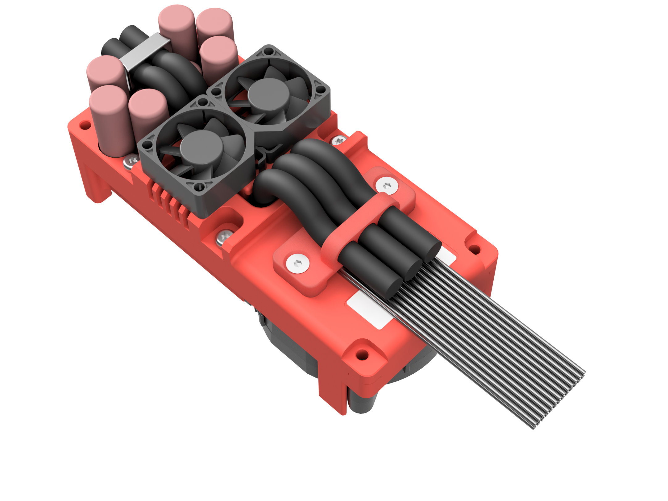
- Raptor Fan edition. Optimized for airborne applications with active air cooling.
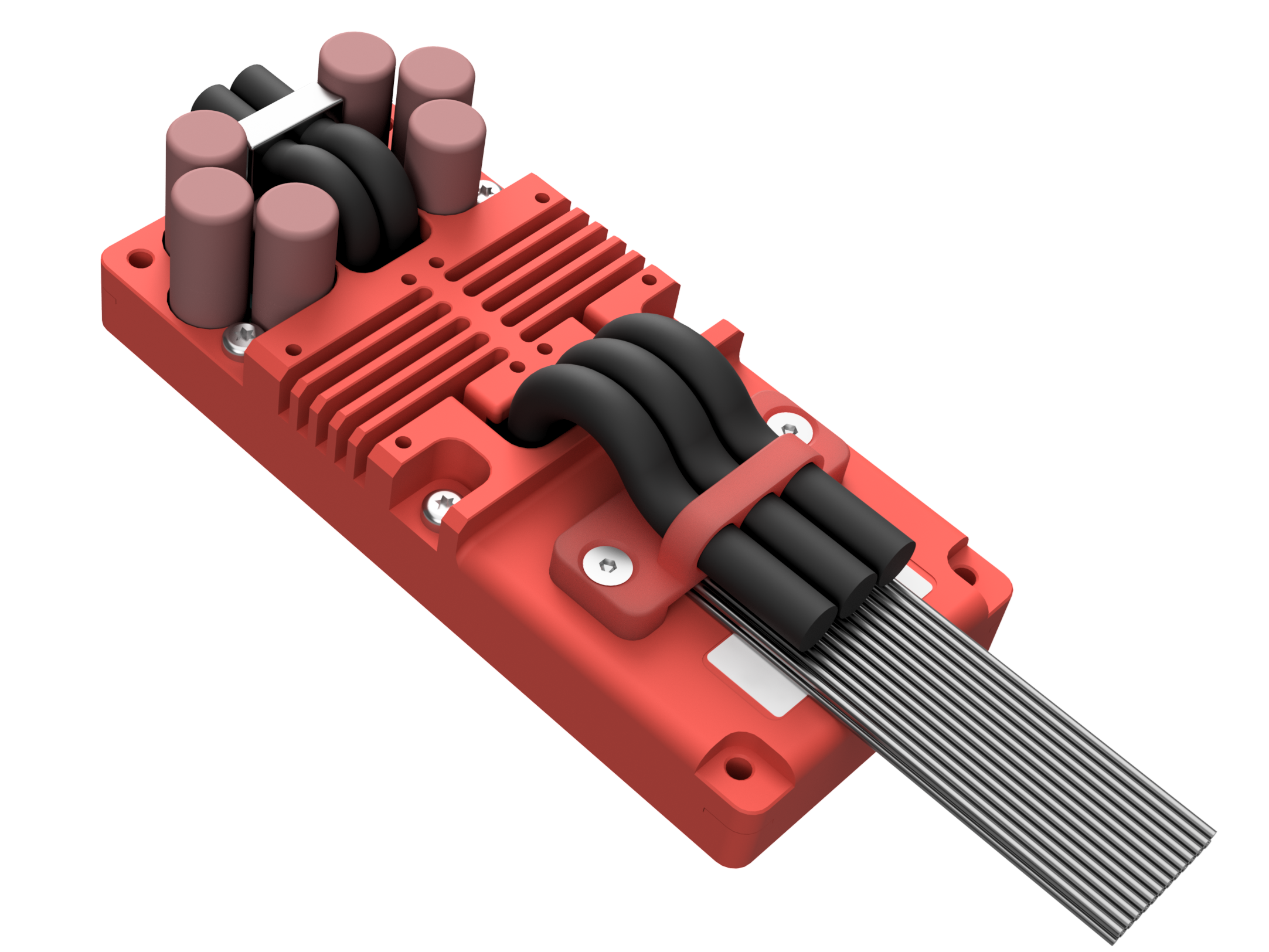
- Raptor Flat edition. Optimized for airborne applications.
- Standard edition
- Raptor Fan edition
- Raptor Flat edition
Applications
- Low-performance e-motorbikes and lightweight electric vehicles
- Electric scooters and personal mobility devices
- Industrial motor drives and pump control
- Electric go-karts and recreational vehicles
- Agricultural and horticultural electric equipment
Applications
- Compact multirotor and quadcopter drone propulsion
- Military micro-UAV and small tactical drone drives
- Aerial survey, mapping, and inspection platforms
- Defense perimeter security and surveillance drones
- First-responder and search-and-rescue aerial systems
- Electronic warfare and signal relay UAV powertrains
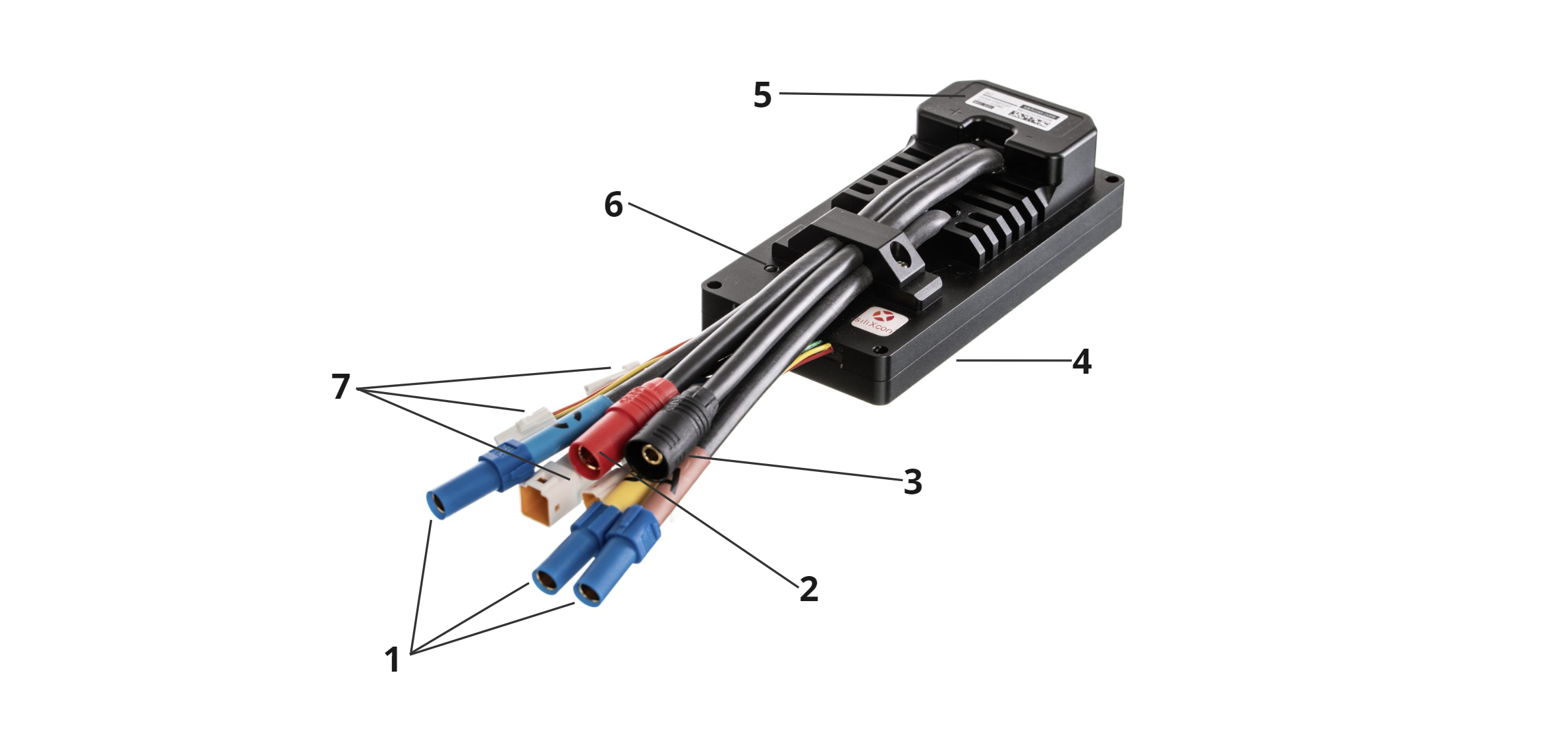
| Position | Name |
|---|---|
| 1 | Motor phase connector - XT150 |
| 2 | Battery + connector - AS150 |
| 3 | Battery - connector - AS150 |
| 4 | Mounting surface |
| 5 | Product label |
| 6 | Status LED |
| 7 | Signal connectors - JST JWPF |
Signal part is connected via several signal connectors - 7. Battery is connected by AS150 connector - 2, 3, XT150 connector is used for motor phases - 1. The controller should be installed by placing the mounting surface - 4 on a flat metal surface and securing it by four screws. Status LED - 6 indicates error states.
Product identification label
Each product is equipped with an identification label containing pertinent information.

| Position | Name |
|---|---|
| 1 | Maximum operating voltage |
| 2 | Country of manufacture |
| 3 | SN QR code |
| 4 | Serial number |
| 5 | Product Name |
| 6 | Order code |
Product variants
The Manufacturer Part Number (MPN) completely specifies the product type and version. When combined with the Firmware Identifier (Basename), it can serve as the ordering code. The MPN is made up of different sections, which are explained in the table below. Typically, only the standard variant is in the stock.
-
The pricing for non-standard MPN is individual. Please contact siliXcon for quotes.
-
For sample orders, selecting a non-standard product variant may result in increased pricing and extended lead times compared to standard samples.
Standard MPNs
Decode MPN
Features
- Assembly code
- Internal HW configuration
- Finish 1
- Finish 2
Details
Complete MPN:
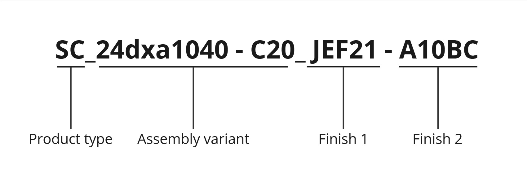
Main PCB assembly variant:
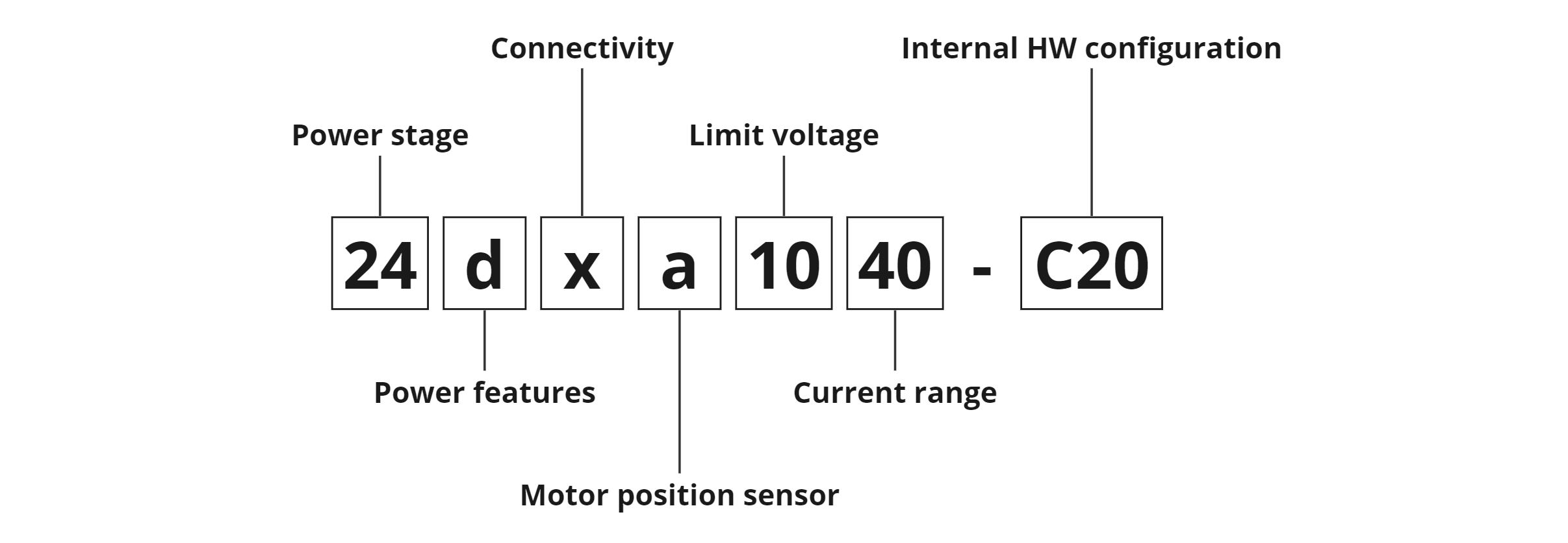
- Power stage: Usually defines a variant of the power stage, occasionally can indicate a special version of the product's PCB.
- Power features: Defines variant of the powering interface. See powering circuit's detailed specification and Controller powering methods.
- Connectivity: Defines variant of the communication interface. See USB, CAN, UART.
- Motor sensors: Defines supported motor position sensors. More information about the particular motor position sensor interface can be found in this section. General information about motor sensors can be found in Motor sensors chapter.
- Voltage: Defines voltage operation range of the controller. Detailed technical specifications can be found in this section.
- Current: Defines current measurement range of the controller.
- Internal HW configuration: see section below
Internal HW configuration:
Internal HW configuration describes selectable modifications in hardware. Each item can be present (marked with 1) or absent (marked with 0). A 12-bit binary number is used for this description and is visualized in hexadecimal form. Not all the options are used, these items are marked as "Reserved".
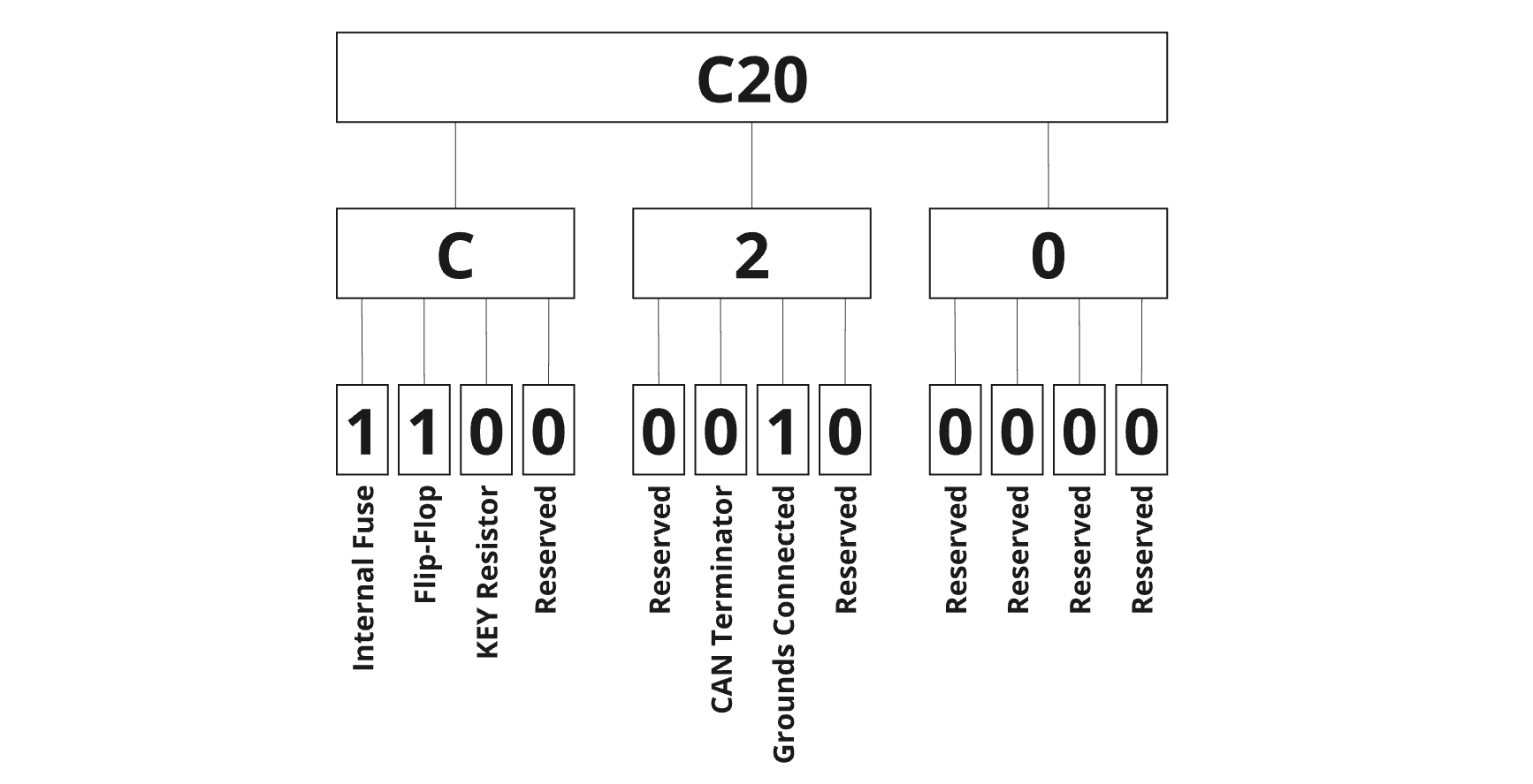
- Powering on method: The device offers several powering methods, defined by
the combination of the following items. For details see powering circuit's detailed specification.
- Internal Fuse
- Flip-flop / One button control
- Constant ON
- Power supply option: Defines isolated supply voltage level on signal connector pin 35.
- CAN terminator: The device has a selectable internal 120-ohm termination resistor. A detailed CAN interface scheme can be found in the CAN communication interface.
- Connected grounds: It is possible to connect two grounding potentials together by the internal jumper.
Finish 1 and Finish 2:
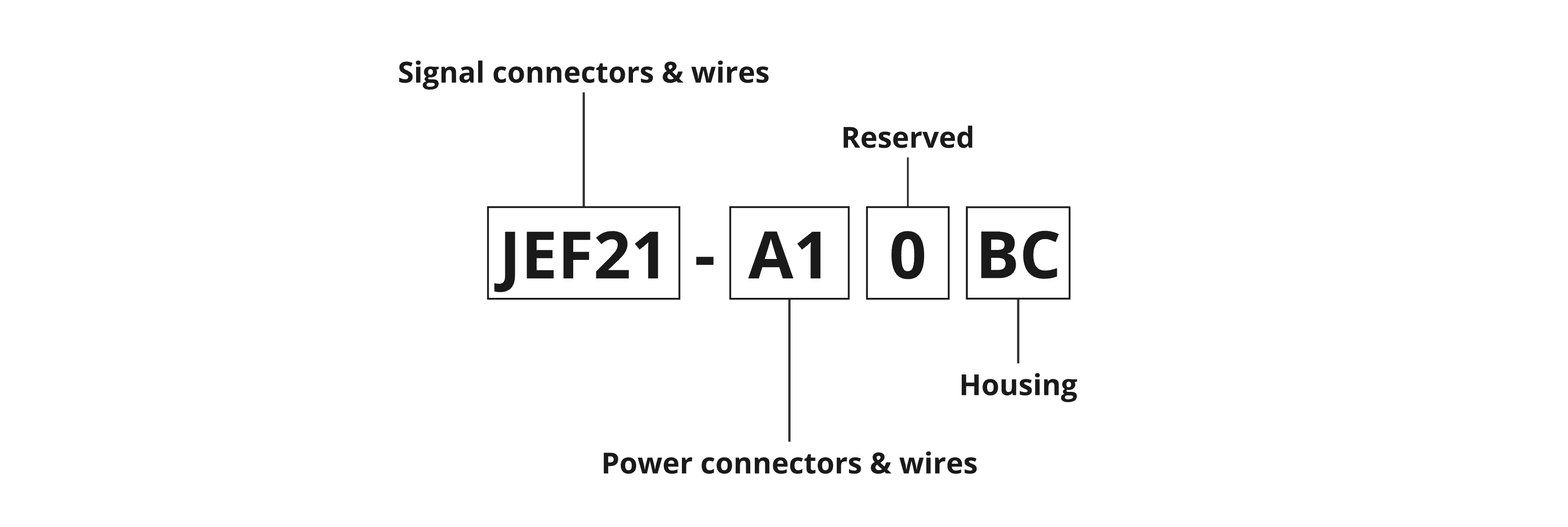
- Signal connectors and wires: Defines used signals connectors and wires.
- Power connectors and wires: Defines used power connectors and wires.
- Housing: Defines housing option.
LED status indicator
The LED status indicator informs about the current state of the motor controller according to table below.
| LED state | Controller condition |
|---|---|
| Permanently turned OFF | Controller is not powered up |
| Briefly turned ON and after a few sec OFF | Controller is powered and fully functional |
| Permanently turned ON | Controller indicates that any of the protections are active. Output current can be limited. |
| Blinking | Controller indicates an internal error and is blinking a 16-bit error code. Controller's power stage is deactivated |
Accessories
Signal connector
- DOUT mating connector: JST 02T-JWPF-VSLE-S
- DIN mating connector: JST 02R-JWPF-VSLE-S
- Motor sensor mating connector: JST 08R-JWPF-VSLE-D
- Control I/O 2 mating connector: JST 08T-JWPF-VSLE-D
- Control I/O 1, UART mating connector: JST 04T-JWPF-VSLE-S
- Power mating connector: JST 03T-JWPF-VSLE-S
- CAN mating connector: JST 03R-JWPF-VSLE-S
- USB mating connector: JST 04R-JWPF-VSLE-S
- Receptacle contact 22-26 AWG SWPR-001T-P025
- Tab contact 22-26 AWG SWPT-001T-P025
- Receptacle contact 22-26 AWG, crimped 0.2m wire SWPR-22LK200-D
- Tab contact 22-26 AWG, crimped 0.2m wire SWPT-22LK200-D
- Crimp tool WC-JWPF
- Removal tool EJ-JWPF
Power connectors
- Motor phase mating connector: Amass XT150-Main
- Battery+ mating connector: Amass AS150-M Red
- Battery- mating connector: Amass AS150-F Black
Set of mating connectors
siliXcon can provide a set of mating connectors for end-application prototyping. The signal JST connectors for the default variant (USB, CAN, UART10V, POWER, CNTRL1, CNTRL2, MSENS, DOUT) are precrimped with 10cm cables. Mating motor phases and battery connectors are included without wires. Please contact siliXcon customer support for more details.
Mounting screws
- 4x M4 or M5 screw. M4 screws are through the heatsink, M5 screws have a thread in the heatsink. Refer to the SC controller drawing.
- for through-hole mounting, minimum thread depth is 1.5 x screw diameter. Tightening torque depends on the material of the mounting base.
Thermal grease
- to improve cooling of the controller, you should apply thermal grease to the mounting area of the controller. Example: Electrolube HTC, AG termopasty HPX