Product specification
- Standard edition
- Raptor Fan edition
- Raptor Flat edition
General specification
| Parameter | value |
|---|---|
| Switching frequency | 20 kHz |
| Maximum motor magnetic field speed | 2 kHz |
| Minimum motor phase inductance | 2.5 μH |
Minimum motor inductance is inductance of one winding (half of inductance between motor terminals). Motor inductance usually drops with increasing current due to saturation of motor magnetic circuit. This effect must be also considered when evaluating motor minimum inductance.
If motor inductance is lower than specified, controller lifetime could be significantly reduced (even orders of magnitude). Low inductance increases electrolytic capacitors ripple current thus their temperature and lifetime.
Electrical specification
Input voltage rating
Maximum input voltage
| Voltage variant | Transistors | Maximum working voltage | Full limitation voltage | Critical error voltage (max) | Li-ion battery nominal voltage | Li-ion series cells count |
|---|---|---|---|---|---|---|
| 08 | 80 V | 67.2 V | 75 V | 80 V | 57.6 V | 16S |
| 10 | 100 V | 84 V | 92 V | 100 V | 72 V | 20S |
Minimum input (supply) voltage
| Voltage variant | Transistors | Minimum working voltage | Threshold voltage | Critical error voltage (min) |
|---|---|---|---|---|
| 08 | 80 V | 18 V | 16 V | 12 V |
| 10 | 100 V | 18 V | 16 V | 12 V |
Terms explanation:
- The controller delivers maximal current without limitation if the battery voltage is below the Maximum working voltage and above the Minimum working voltage.
- The output current is proportionally limited if the battery voltage is above the Maximum working voltage and below the Full limitation voltage. This is indicated by the "Overvoltage" status.
- The output current is fully limited if the battery voltage is above the Full limitation voltage and below the Critical error voltage (max). This state is indicated by the "Overvoltage" status. The controller automatically recovers if the voltage falls below the Full limitation voltage.
- The controller falls into critical error if the battery voltage exceeds the Critical error voltage (max). The controller can be permanently damaged in this region and does not recover automatically, it needs to be turned OFF and ON again.
- The output current is proportionally limited if the battery voltage is below the Minimum working voltage and above the Threshold voltage. This is indicated by the "Undervoltage" status.
- The output current is fully limited if the battery voltage is below the Threshold voltage and above the Critical error voltage (min). This state is indicated by the "Undervoltage" status. The controller automatically recovers if the voltage rises above the Threshold voltage.
- The controller falls into critical error if the battery voltage falls below the Critical error voltage (min). The controller does not recover automatically, it needs to be turned OFF and ON again.
DC bus capacitance
| Voltage variant | Capacitance [uF] |
|---|---|
| 08 | 1980 |
| 10 | 1350 |
Output current and power rating
- VECTOR driver
- BLDC driver
| Nominal (continuous) performance * | 24xxx0840 (Standard) | 24xxx1040 (Standard) | 25xxx1060 (Raptor Flat) | 25xxx1060 (Raptor Fan) |
|---|---|---|---|---|
| Maximum continuous power dissipation (60°C heatsink) | 120 W | 120 W | 100 W | 80 W |
| Nominal power (for maximum input voltage) | 12 kW @ 68 V | 13.5 kW @ 84 V | TBD | TBD |
| Nominal phase current | 205 A (145 Arms) | 185 A (130 Arms) | TBD | TBD |
| Battery current | 180 A | 162 A | TBD | TBD |
* For FAN edition: assuming fan installed, air path not obscured, air temperature 20°C. For others: placing the controller on infinite heatsink with 60°C temperature. Under these conditions the controller will deliver nominal (continuous) performance.
For Raptor editions, the top-side fans can be installed on request for further continuous performance improvement.
| Peak performance * | 24xxx0840 (Standard) | 24xxx1040 (Standard) | 25xxx1060 (Raptor) |
|---|---|---|---|
| Peak power (10 sec) | 20 kW @ 68 V | 20.4 kW @ 84 V | 20.4 kW @ 84 V |
| Peak phase current (10 sec) | 340 A (240 Arms) | 280 A (198 Arms) | 280 A (198 Arms) |
* Starting at 35°C, the controller will deliver peak performance for 10 seconds. Then, derating will progress until thermal equilibrium is found.
| Nominal (continuous) performance * | 24xxx0840 (Standard) | 24xxx1040 (Standard) | 25xxx1060 (Raptor Flat) | 25xxx1060 (Raptor Fan) |
|---|---|---|---|---|
| Maximum continuous power dissipation (60°C heatsink) | 120 W | 120 W | 100 W | 80 W |
| Nominal power (for maximum input voltage) | 13.9 kW @ 68 V | 16 kW @ 84 V | TBD | TBD |
| Nominal phase current | 205 A | 190 A | TBD | TBD |
| Battery current | 205 A | 190 A | TBD | TBD |
* For FAN edition: assuming fan installed, air path not obscured, air temperature 20°C. For others: placing the controller on infinite heatsink with 60°C temperature. Under these conditions the controller will deliver nominal (continuous) performance.
| Peak performance * | 24xxx0840 (Standard) | 24xxx1040 (Standard) | 25xxx1060 (Raptor) |
|---|---|---|---|
| Peak power (10 sec) | 21.1 kW @ 68 V | 23.5 kW @ 84 V | 23.5 kW @ 84 V |
| Peak phase current (10 sec) | 340 A | 280 A | 280 A |
* Starting at 35°C, the controller will deliver peak performance for 10 seconds. Then, derating will progress until thermal equilibrium is found.
| Fixed phase current limits | 24xxx0640, 24xxx0840, 24xxx1040 | 25xxx1060 |
|---|---|---|
| RMS current limit 1/ | 300 Arms | 300 Arms |
| Burst current limit 2/ | 400 A | 600 A |
1/ Irrespective of the actual temperature conditions, the immediate output current will be clamped to these values by the I2R limiter in the order of seconds. When motor is rotating, power losses are divided between all three phases and the controller is able to supply higher per-phase current amplitude. When the device is super-cooled from outside, this is the maximum theoretical continuous RMS current.
2/ This current can be delivered in short bursts and reflects the current measurement range of every variant. The sufficient margin for current ripple of the switching waveform must be accomodated within the range. Any higher current triggers DTC / active short circuit protection.
Measurement accuracy
| Measurement | Accuracy |
|---|---|
| Phase current | ±5 % |
| DC current | ±5 % |
| Input DC voltage | ±5 % |
| GPIO input voltage | ±2 % |
Thermal specification
Maximum power losses
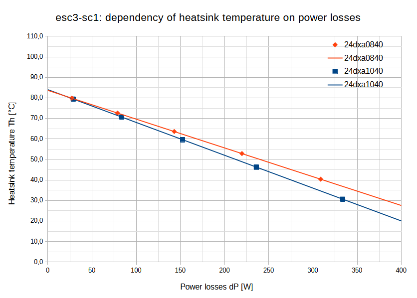
Controller maximum temperature is internally limited to approximately 100°C. The maximum output current (or maximum power losses) for this limiting temperature is given by the temperature of the heatsink. Dependencies are given in the following graphs.
All the data in the graphs below are valid for VECTOR control algorithm.
- Standard edition
- Raptor Flat edition
- Raptor Fan edition
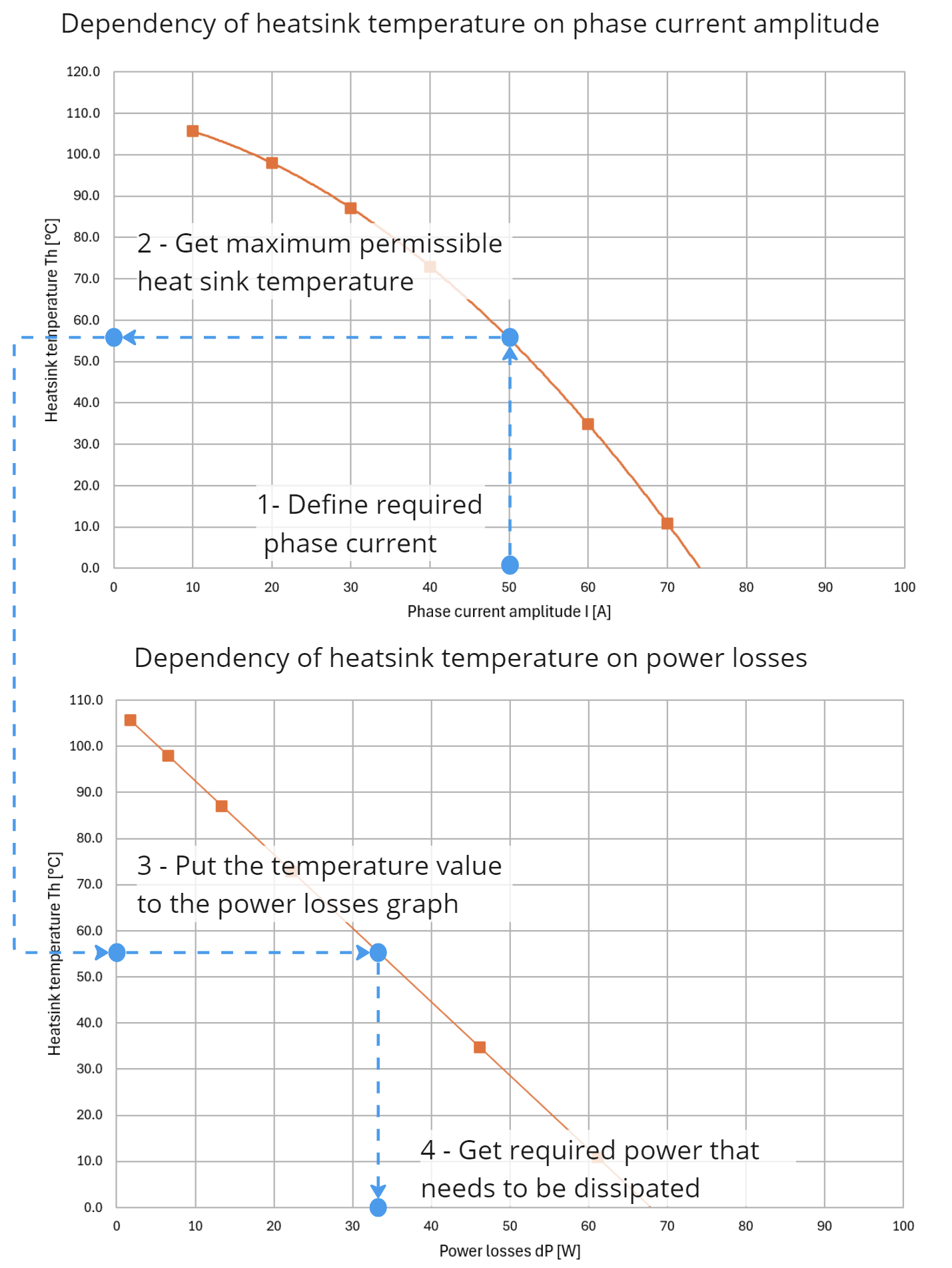
This example with AX controller shows on how to get required heatsink thermal
resistance based on the required phase current amplitude and surrounding
temperature.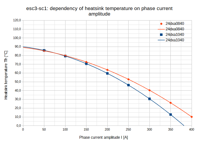
Example on how to get heatsink thermal resistance
| Parameter | Value | Conditions |
|---|---|---|
| Maximum continuous power dissipation | TBD | Controller thermally connected to infinite heatsink at max 60 °C |
| TBD | Controller in still air at 25 °C | |
| Thermal resistance | TBD | To the bottom pad of the housing |
Thermal dependency data is not yet available for Raptor editions. Please refer to the power dissipation calculator below.
| Parameter | Value | Conditions |
|---|---|---|
| Maximum continuous power dissipation | TBD | Fan installed, air path not obscured, air temperature 20 °C |
Thermal dependency data is not yet available for Raptor editions. Please refer to the power dissipation calculator below.
Power losses calculator
Controller power losses are affected by the two main factors: motor phase current and DC link voltage. The following calculator can be used for rough estimate (~10% accuracy) of power losses in the controller. Calculation is valid for VECTOR driver.
Environmental specification
- Standard edition
- Raptor editions
| Parameter | Value |
|---|---|
| Operation temperature (no limitation*) | -20°C .. 60°C |
| Operation temperature (with power limitation*) | -20°C .. 80°C |
| Humidity | 5 % .. 85 % (not tested) |
| Ingress of water (connectors unmated) | IP40 |
| Ingress of water (connectors mated) | IPx5 |
*power output limitation depends on cooling, not only on ambient temperature
| Parameter | Value |
|---|---|
| Operation temperature (no limitation*) | -20°C .. 60°C |
| Operation temperature (with power limitation*) | -20°C .. 80°C |
| Humidity | 5 % .. 85 % (not tested) |
| Ingress protection | IP40 |
*power output limitation depends on cooling, not only on ambient temperature
Higher ingress protection rating possible on demand.
Standards compliance
EMC
| Subject | Standard |
|---|---|
| Bulk Current Injection | ISO 11452-4: 2020 |
| Radiated Immunity | ISO 11452-2: 2019 |
| Radiated Emissions | ČSN EN 55025, ed. 3, art. 6.5 |