SL MV
The middle voltage edition of the SL controller. Modified for working voltages up to 118 V. Mandatory external SL capacitor bank required.
Applications
- Midsize e-motorbikes and electric motorcycles
- Small electric cars and neighborhood electric vehicles (NEVs)
- Marine electric propulsion
- Industrial automation and high-power servo drives
- Material handling and warehouse robotics
- Research and development platforms
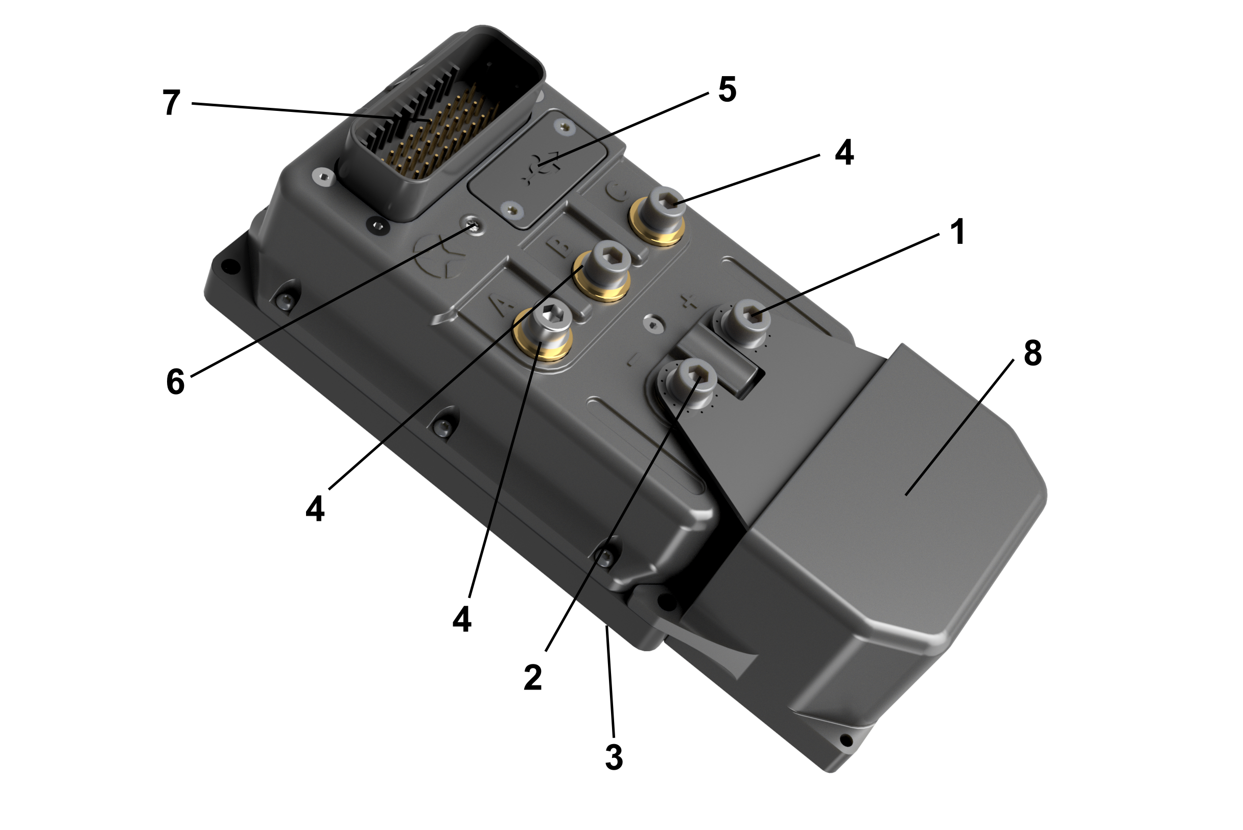
| Position | Name |
|---|---|
| 1 | Battery + terminal |
| 2 | Battery - terminal |
| 3 | Mounting surface |
| 4 | Motor phase terminal |
| 5 | USB cover / Vent plug |
| 6 | Status LED |
| 7 | Signal connector - Ampseal |
| 8 | Additional DC link capacitor* |
Note *: only in the middle voltage edition
Signal part is connected via the signal connector - 7. Battery is connected to M6 terminals - 1, 2, as well as motor phases - 4. The controller should be installed by placing the mounting surface - 3 on a flat metal surface and securing it by four screws. Status LED - 6 indicates error states. USB-B programming connector is under the cover - 5.
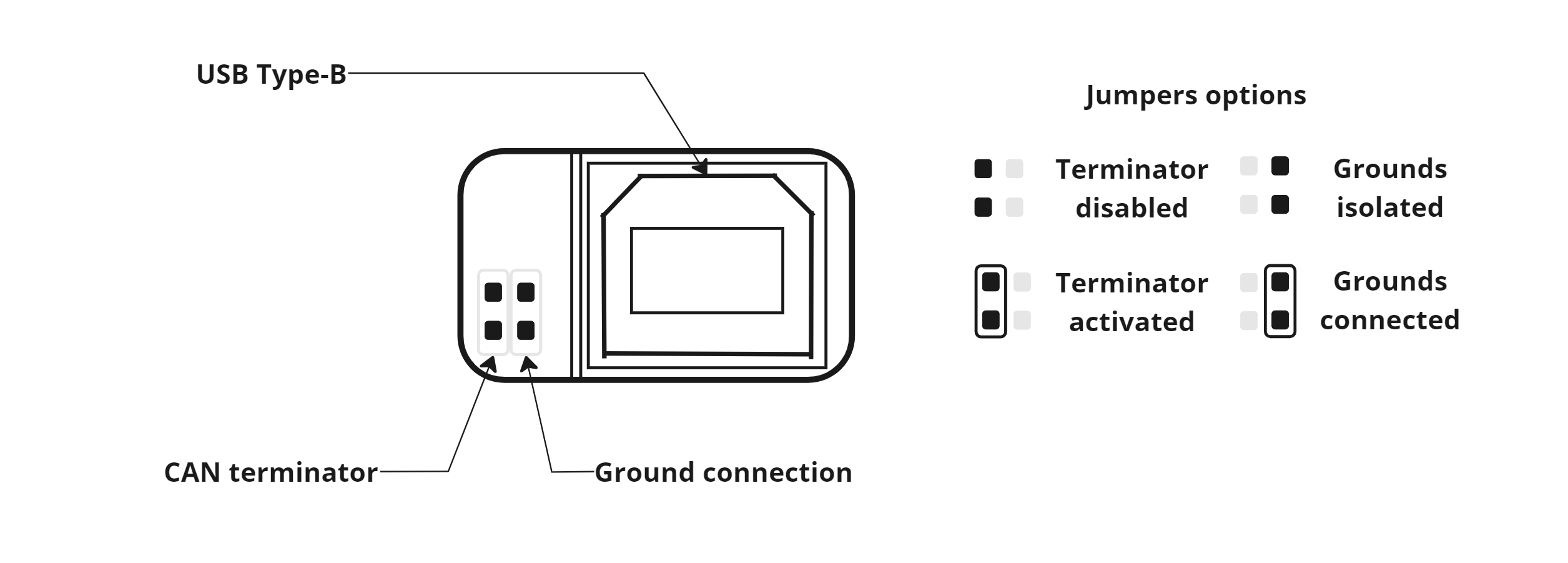
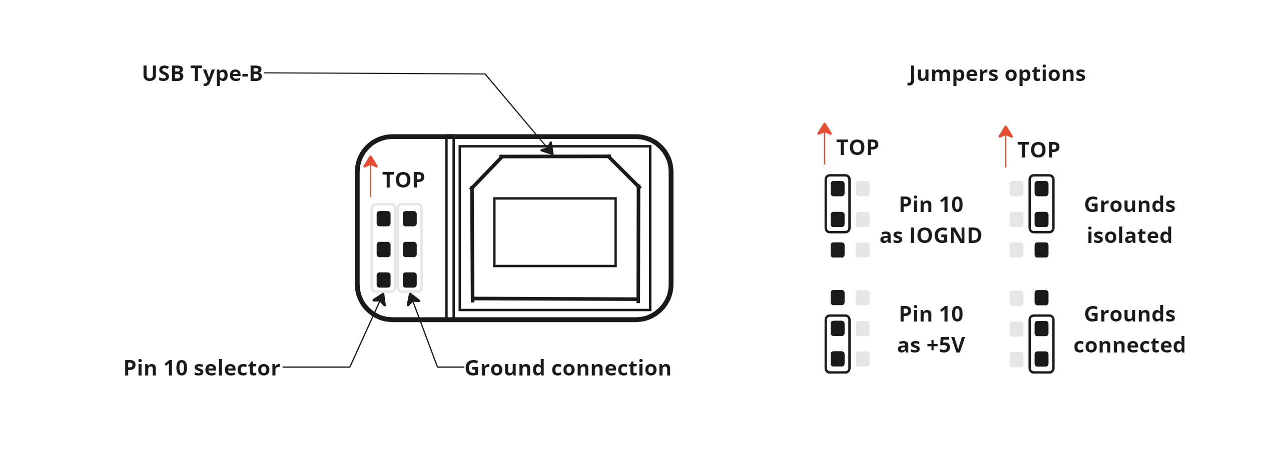
Selectable jumpers
SL controller can be equipped with two versions of the jumper board. Unfortunately, the board version is not reflected in the controller's MPN, and it is necessary to identify them by physical appearance.
Both versions' selectable jumpers are located under the USB cover.
- New version
- Old version
There are two jumpers with 4 pins in total. The jumpers' localization and function are depicted in the picture below.
There are two jumpers with 6 pins in total. The jumpers' localization and function are depicted in the picture below.
Product identification label
Each product is equipped with an identification label containing pertinent information.

| Position | Name |
|---|---|
| 1 | Maximum operating voltage |
| 2 | Country of manufacture |
| 3 | SN QR code |
| 4 | Serial number |
| 5 | Product Name |
| 6 | Order code |
LED status indicator
The LED status indicator informs about the current state of the motor controller according to table below.
| LED color | LED state | Controller condition |
|---|---|---|
| None | Permanently turned OFF | The controller is not powered on. |
| Red | Permanently turned ON | The controller is turned on and the power stage is not ready. The controller indicates that any of the protections are active. |
| Red | Blinking | The controller is turned on and the power stage is not ready. The controller indicates an internal error and is blinking a 16-bit error code. |
| Green | Permanently turned ON | The controller is turned on and the power stage is ready (the motor is not driven). |
| Green | Blinking | The controller is turned on and the power stage is ready (the motor is not driven). The controller indicates an error code of the common block. |
| Blue | Permanently turned ON | The controller is turned on and the power stage is ready and the motor is driven. |
| Purple | Permanently turned ON | The controller is turned on and the power stage is ready and the motor is driven. The controller indicates that any of the protections are active and output current could be limited. |
| Yellow | Permanently turned ON | The controller is turned on and the power stage is ready (the motor is not driven). The controller indicates that any of the protections are active. |
Accessories
Signal connector
- mating connector: AMPSEAL 35pos, Black, 16-20 AWG 776164-1
- mating connector: AMPSEAL 35pos, Black, 20-24 AWG 2371885-1
- back shell: 2389807-1
- connector position assurance: 2373965-1
- sealing plug 16-20 AWG: 770678-1
- sealing plug 20-24 AWG: 776364-1
- crimp terminals 16-20 AWG, Pre-tin plated: 770520-1
- crimp terminals 20-22 AWG, Pre-tin plated: 770520-5
- crimp terminals 22-24 AWG, Pre-tin plated: 770520-6
- crimp tool 16-20 AWG: 2217748-1
- crimp tool 20-22 AWG: 2396182-1
- crimp tool 22-24 AWG: 2396101-1
Jumper
- jumper with handle: e.g. Fischer Elektronik CAB 9 GS
Power connectors
- mating connector: M6 cable lug 10 - 50 mm2 + M6 screw. Terminal thread length is 13 mm, maximum tightening torque is 10 Nm.
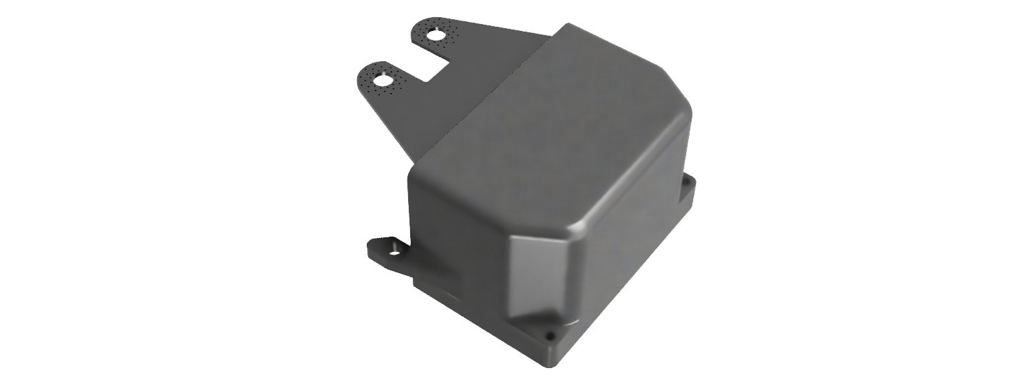
External capacitor bank
SL controller might be equipped with an external capacitor bank. The capacitor bank is connected to the controller terminals under the battery+ and battery- cable lugs. Usage of this capacitor bank is mandatory for the middle voltage edition of the controller. For other editions, usage is optional and depends on the application requirements.
The product number for purchasing: SL capacitor bank.
Mounting screws
- 4x M5 or M6 screw. M5 screws are through the heatsink, M6 screws have a thread in the heatsink. Refer to the SL controller drawing.
- for through-hole mounting, minimum thread depth is 1.5 x screw diameter. Tightening torque depends on the material of the mounting base.
Thermal grease
- to improve cooling of the controller, you should apply thermal grease to the mounting area of the controller. Example: Electrolube HTC, AG termopasty HPX