Product overview
SX controller
18 kW brushless motor controller is a compact and robust solution featuring a single signal connector (superseal 1.0). With an impressive capability to deliver up to 250 A rms, this controller is designed to power small e-motorbikes and larger e-scooters. Its M6 power terminals, crafted from brass, ensure minimal power losses. This versatile controller is well-suited for various applications, including automotive, marine, aerospace, and more, with a primary emphasis on high-series production.
Controller editions
SX controller may come in different flavours, called editions. Each edition is tailored to specific application requirements and may differ in dimensions, maximum working voltage and signal connector functionality. Right now, following editions of the SX controller exists:
- standard edition. Maximum working voltage is 84 V.
- middle voltage edition. Modified for working voltages up to 118 V.
- Standard edition
- Middle voltage edition
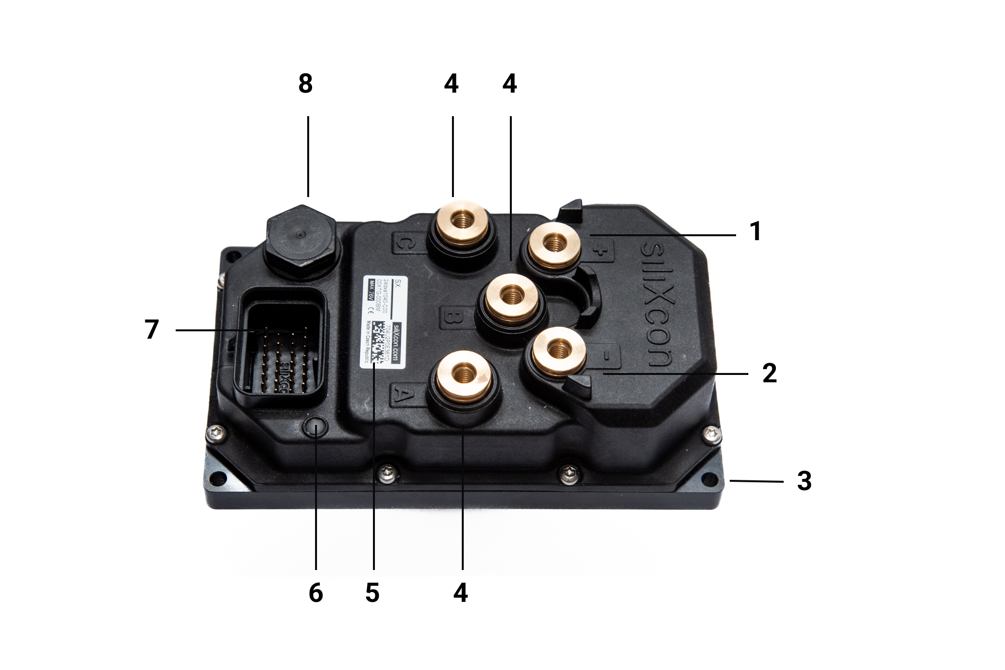
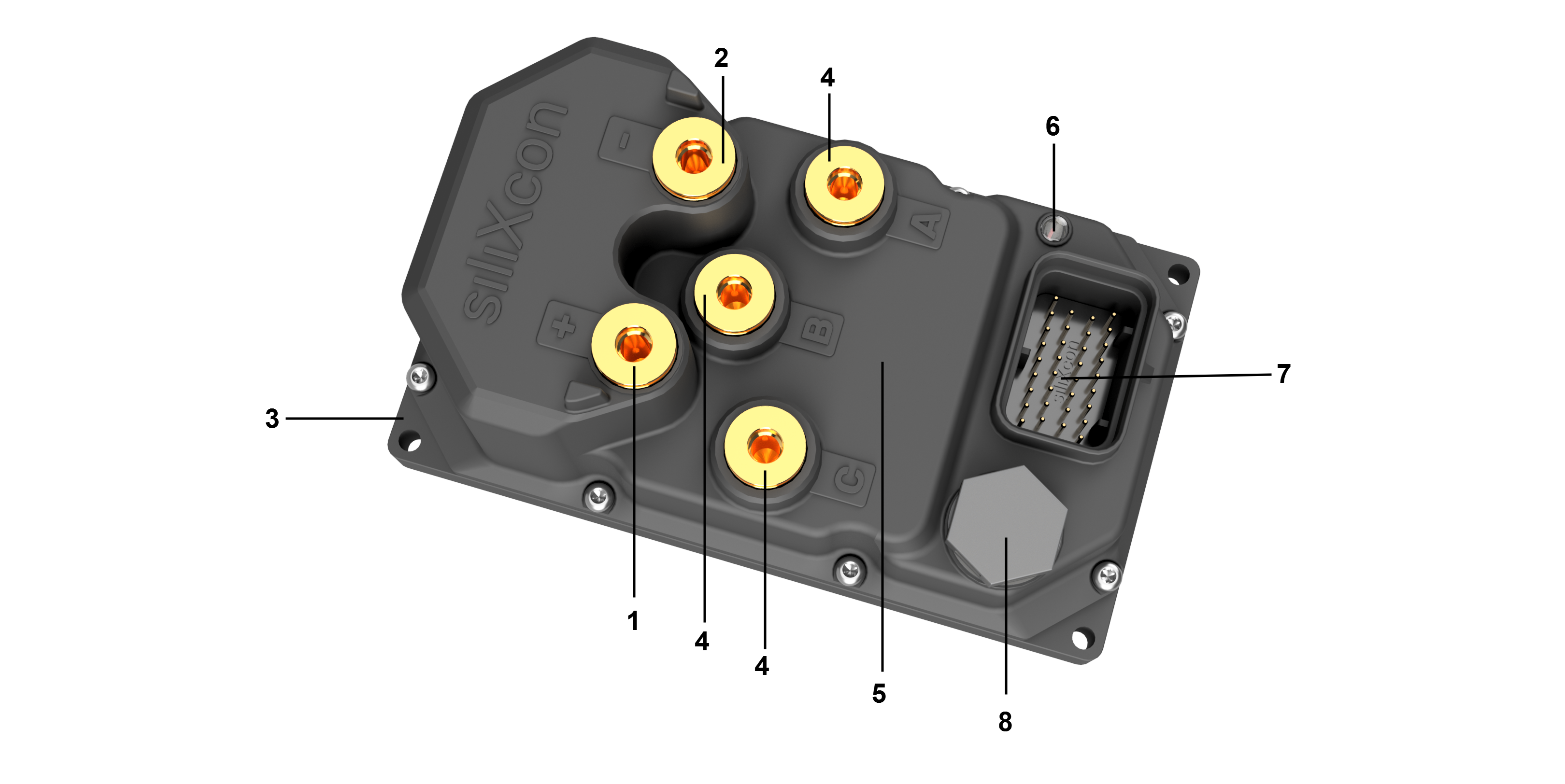
| Position | Name |
|---|---|
| 1 | Battery + terminal |
| 2 | Battery - terminal |
| 3 | Mounting surface |
| 4 | Motor phase terminal |
| 5 | Product label |
| 6 | Status LED |
| 7 | Signal connector - Superseal 1.0 |
| 8 | USB cover / Vent plug |
Signal part is connected via the signal connector - 7. Battery is connected to M6 terminals - 1, 2, as well as motor phases - 4. The controller should be installed by placing the mounting surface - 3 on a flat metal surface and securing it by four screws. Status LED - 6 indicates error states. USB-C programming connector is under the cover - 8.
Jumpers position
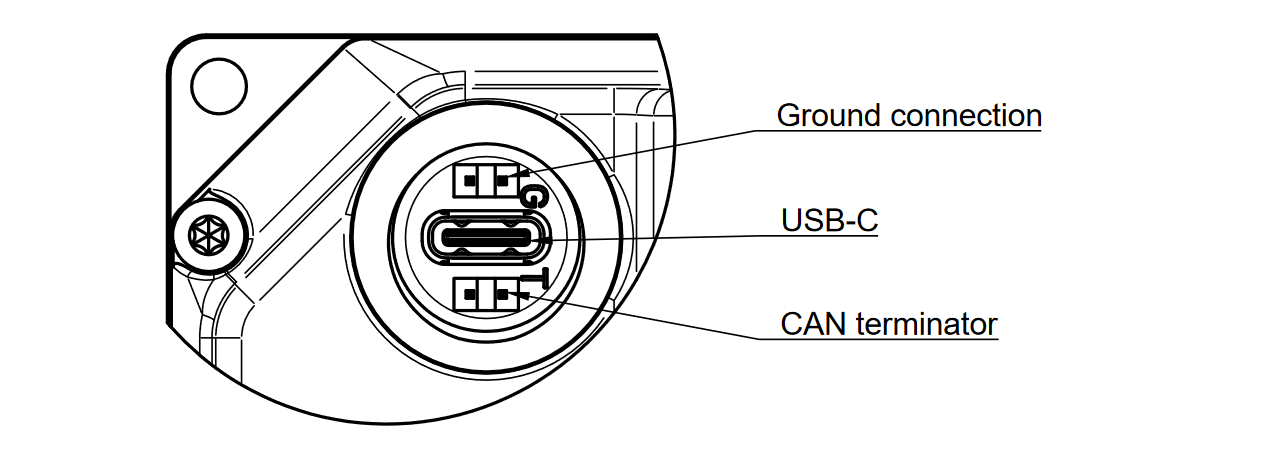
There are also two low profile jumpers under the USB cover. Position of the jumpers and its function is depicted on the picture below.
Product identification label
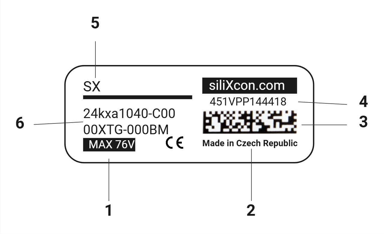
Each product is equipped with an identification label containing pertinent information.
| Position | Name |
|---|---|
| 1 | Maximum operating voltage |
| 2 | Country of manufacture |
| 3 | SN QR code |
| 4 | Serial number |
| 5 | Product Name |
| 6 | Order code |
Product variants
The Manufacturer Part Number (MPN) completely specifies the product type and version. When combined with the Firmware Identifier (Basename), it can serve as the ordering code. The MPN is made up of different sections, which are explained in the table below. Typically, only the standard variant is in the stock.
-
The pricing for non-standard MPN is individual. Please contact siliXcon for quotes.
-
For sample orders, selecting a non-standard product variant may result in increased pricing and extended lead times compared to standard samples.
Standard MPNs
Decode MPN
Features
- Assembly code
- Internal HW configuration
- Finish 1 (Power PCB assembly variant)
- Finish 2
Details
Complete MPN:
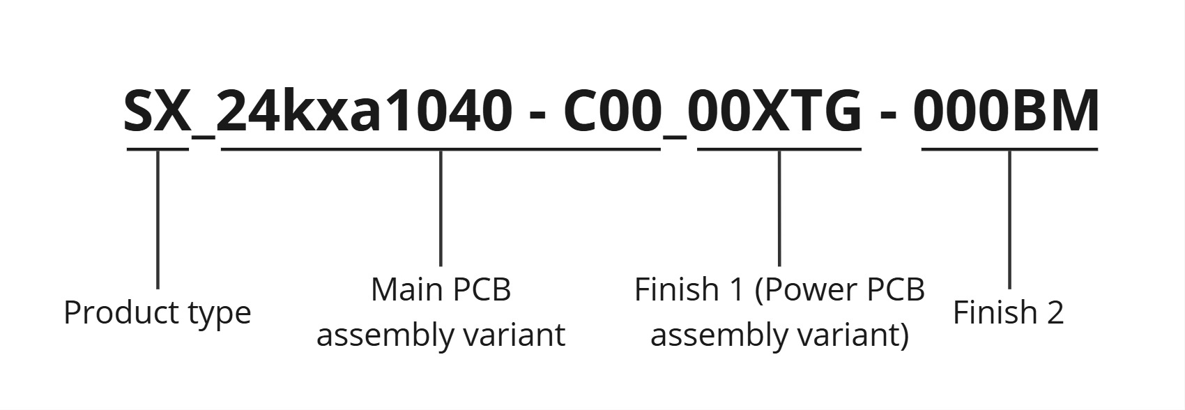
Main PCB assembly variant:
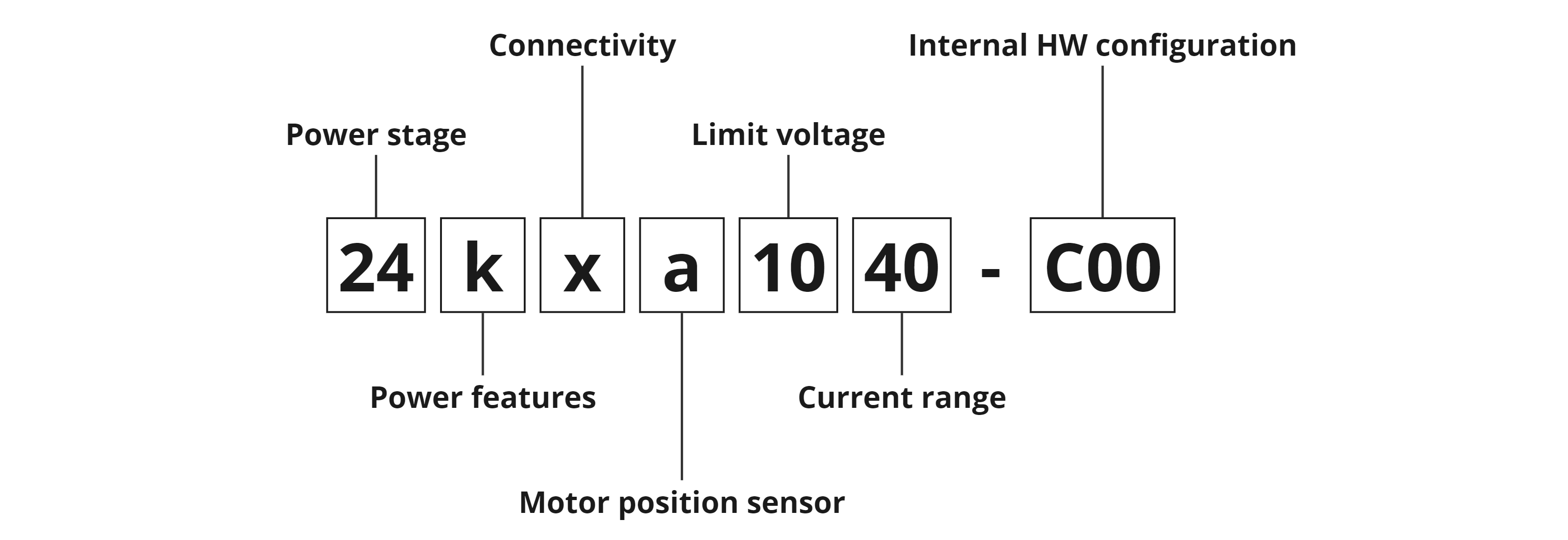
- Power stage: Usually defines a variant of the power stage, occasionally can indicate a special version of the product's PCB.
- Power features: Defines variant of the powering interface. See powering circuit's detailed specification and Controller powering methods.
- Connectivity: Defines variant of the communication interface. See USB, CAN, UART.
- Motor sensors: Defines supported motor position sensors. More information about the particular motor position sensor interface can be found in this section. General information about motor sensors can be found in Motor sensors chapter.
- Voltage: Defines voltage operation range of the controller. Detailed technical specifications can be found in this section.
- Current: Defines current measurement range of the controller.
- Internal HW configuration: see section below
Internal HW configuration:
Internal HW configuration describes selectable modifications in hardware. Each item can be present (marked with 1) or absent (marked with 0). A 12-bit binary number is used for this description and is visualized in hexadecimal form. Not all the options are used, these items are marked as "Reserved".
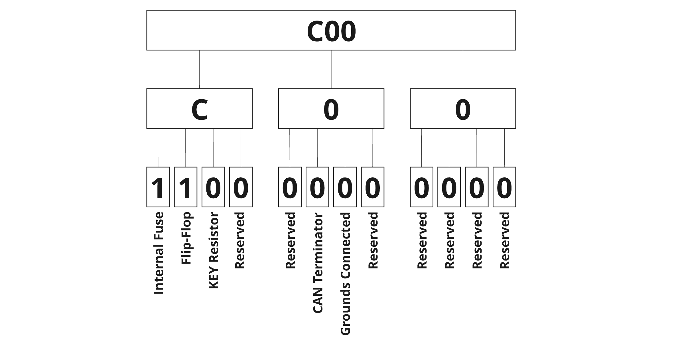
- Powering on method: The device offers several powering methods, defined by
the combination of the following items. For details see powering circuit's detailed specification.
- Internal Fuse
- Flip-flop / One button control
- Constant ON
- Power supply option: Defines isolated supply voltage level on signal connector pin 35.
- CAN terminator: The device has a selectable internal 120-ohm termination resistor. A detailed CAN interface scheme can be found in the CAN communication interface.
- Connected grounds: It is possible to connect two grounding potentials together by the internal jumper.
Finish 1 (Power PCB assembly variant):

- Connectivity: Defines connectivity option of the power board.
- Power terminals: Defines used power terminals.
- Jumpers: Defines jumpers variant.
Finish 2:

- Housing: Defines housing option.
LED status indicator
The LED status indicator informs about the current state of the motor controller according to table below.
| LED state | Controller condition |
|---|---|
| Permanently turned OFF | Controller is not powered up |
| Briefly turned ON and after a few sec OFF | Controller is powered and fully functional |
| Permanently turned ON | Controller indicates that any of the protections are active. Output current can be limited. |
| Blinking | Controller indicates an internal error and is blinking a 16-bit error code. Controller's power stage is deactivated |
Accessories
Signal connector
- mating connector: SUPERSEAL 1.0 mm 34pos 4-1437290-0
- crimp terminals 22AWG: 3-1447221-5
- crimp terminals 20AWG: 3-1447221-4
- crimp terminals 16-18AWG: 3-1447221-3
- cavity plug: 4-1437284-3
- crimp tool 22AWG: 1729173-1
- crimp tool 16-18-20AWG: 91390-1
Jumper
- low profile jumper: e.g. Fischer Elektronik CAB 6 05 GS
Power connectors
- mating connector: M6 cable lug 10 - 50 mm2 + M6 screw. Terminal thread length is 13 mm, maximum tightening torque is 10 Nm.
Mounting screws
- 4x M4 or M5 screw. M4 screws are through the heatsink, M5 screws have a thread in the heatsink. Refer to the SX controller drawing.
- for through-hole mounting, minimum thread depth is 1.5 x screw diameter. Tightening torque depends on the material of the mounting base.
Thermal grease
- to improve cooling of the controller, you should apply thermal grease to the mounting area of the controller. Example: Electrolube HTC, AG termopasty HPX