Pinout and I/O specification
Pinout
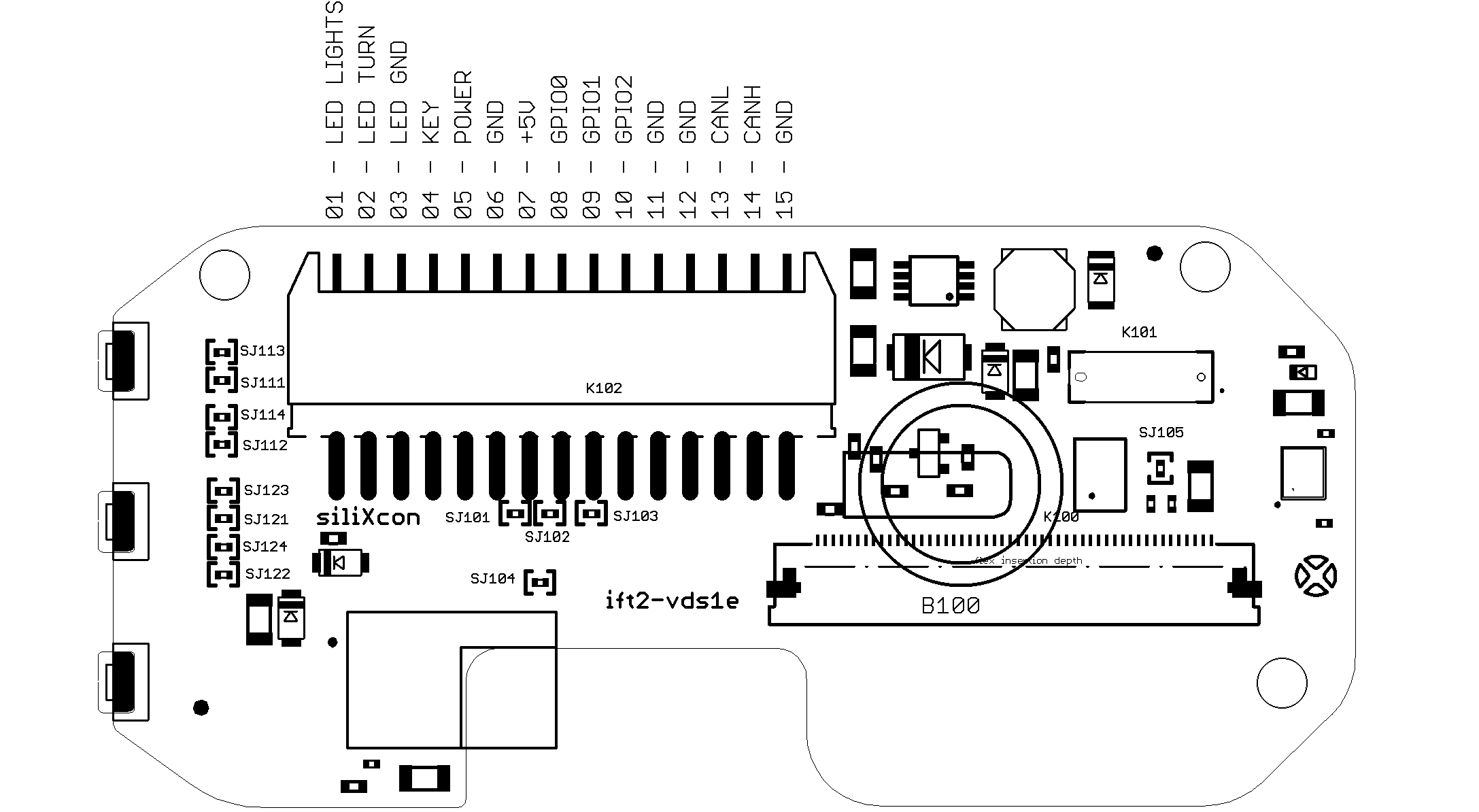
Previous PCB revision.
Conector pinout is the same, only positions of jumpers are different.
Pinout
| Name | pin number |
|---|---|
| LED LIGHTS | 1 |
| LED TURN | 2 |
| LED GND | 3 |
| KEY | 4 |
| POWER | 5 |
| GND | 6 |
| +5V | 7 |
| GPIO0 | 8 |
| GPIO1 | 9 |
| GPIO2 | 10 |
| GND | 11 |
| GND | 12 |
| CANL | 13 |
| CANH | 14 |
| GND | 15 |
Main connector PN
| Name | PN | Notes |
|---|---|---|
| Onboard connector | 502352-1500 | 15-pin Molex DuraClick |
| Mating connector | 5023511500 | |
| Crimp terminal | 5600850101 | 22-26 AWG wire |
Signal connector pinout
Below are specified currently active cable variants.
- S04
This variant is equipped with two cables ending with JST JWPF connectors. Both cables have a length of 400 mm. The first cable is designed as an interface connection to a siliXcon controller. The second cable should be used as an interface for external components (map switch and 12V system).
Cable one
- The cable length is 400 mm
- The power connector matches with the controller's Power, Key and GND pins
- CAN connector matches with controller's CANL, CANH, and CAN GND pins
Power connector

CAN connector

Cable pinout
| Power connector pin number | CAN connector pin number | Pin name | Wire colour |
|---|---|---|---|
| 1 | - | KEY | Brown |
| 2 | - | POWER | Pink |
| 3 | - | POWER GND | White |
| - | 1 | CAN GND | Black |
| - | 2 | CANH | Yellow |
| - | 3 | CANL | Green |
Cable two
- The cable length is 400 mm
- Control 1 connector is dedicated to a push map button
- Control 2 connector:
- GPIO1: Left indicator signal*
- GPIO2: Right indicator signal*
- LEDLights: Hi-Beam indicator signal**
- LED GND: 12 V ground
*GPIO GND is the reference potential
**LED GND is the reference potential
Control 1 connector

Control 2 connector

Cable pinout
| Control 1 connector pin number | Control 2 connector pin number | Pin name | Wire colour |
|---|---|---|---|
| 1 | - | GPIO0 | Brown |
| 2 | - | GPIO GND | White |
| - | 1 | GPIO1 | Green |
| - | 2 | LED LIGHTS | Pink |
| - | 3 | GPIO2 | Yellow |
| - | 4 | LED GND | Grey |
Pin detailed specifications
Power circuit
Function
The power circuit provides power to the display. The KEY input is designed to be connected to the battery voltage through the controller's KEY pin. Power to the internal SMPS (Switched-Mode Power Supply) is controlled by an electronic switch. There are several options for powering on/off, which are described below.
- Constant on
- Flip-flop
- Flip-flop with button
- Activation input
- The device turns on when power is applied and off when removed.
Internal HW configuration for this variant:
- Key resistor - Attached
- Flip-flop - Removed
- Powering by button - Removed
- The device turns on once a voltage above 10V is applied to the power pin. The latching function of the flip-flop ensures that it remains turned on even when the voltage is disconnected.
- The device turns off once a voltage below 1V is applied to the power pin.
- It is also possible to turn off the device by FW.
Internal HW configuration for this variant:
- Key resistor - Removed
- Flip-flop - Attached
- Powering by button - Removed
- The device turns on once a voltage above 10V is applied to the power pin. The latching function of the flip-flop ensures that it remains turned on even when the voltage is disconnected.
- The device can be alternatively turned on by a short press of the button #1.
- The device turns off once a voltage below 1V is applied to the power pin .
- The device can be alternatively turned off by a long press of the button #1.
- It is also possible to turn off the device by FW.
All the other devices connected to the POWER pin also receive the powering signal - The device could turn on/off other devices.
Internal HW configuration for this variant:
- Key resistor - Removed
- Flip-flop - Attached
- Powering by button - Attached
- The device turns on once a voltage above 10V is permanently applied to the power pin.
- The device turns off once the voltage is removed from the power pin.
Internal HW configuration for this variant:
- Key resistor - Removed
- Flip-flop - Removed
- Powering by button - Removed
Scheme
Jumpers
| Jumper | Description |
|---|---|
| S101 | Enable flip-flop |
| S102 | Enable activation input |
| S103 | Enable key resistor (contant on) |
| S104 | Enable display turn on by BTN1 |
One of these jumpers must be enabled - S101 or S102. Otherwise, display will not turn on.
Specification
| Name | Function | Operating range | Maximum rating | Protection |
|---|---|---|---|---|
| KEY | power input for control electronics | 0 .. 76 V | one-time fuse | |
| POWER | power control input (switches device on/off), min. 10 V for on, max. 1 V for off | 0 .. 76 V | high impedance | |
| POWER GND | power input ground | 100 mA |
Voltage between 1 V and 10 V is not allowed, because the device is in a non-defined state and could be damaged in such a situation.
Analog inputs
Function
The display is equipped with three analog inputs that can be used to connect external accessories. The reference potential is shared with the main GND. +5V source for driving external components is also available. The operating range of the inputs is 0 - 12 V.
Analog inputs are not galvanically isolated from the power GND
Scheme
Specification
| Name | Function | Operating range | Maximum rating |
|---|---|---|---|
| GPIO GND | GND, internally connected POWER GND | 50 mA | |
| +5V | 5 V power supply | 5 V / 50 mA | |
| GPIO0 | Input, max. 2% measurement error | 0 .. 12 V | 0 V .. 16 V |
| GPIO1 | Input, max. 2% measurement error | 0 .. 12 V | 0 V .. 16 V |
| GPIO3 | Input, max. 2% measurement error | 0 .. 12 V | 0 V .. 16 V |
12V inputs
Function
The display can process 12V signals for the Turn and Hi-beam light indicator LEDs. These inputs are galvanically isolated from the main Power GND. It is also possible to control the LEDs by firmware (FW) if the Turn LED by FW respectively Light LED by FW configuration is selected.
The 12V LED inputs are galvanically isolated from the POWER GND.
Scheme
Jumpers
You can change, if the LED is controlled by MCU or by external 12V input.
X mean, connect this jumper
LED 2 - green turn signal
| Jumper | LED-12V | LED-mcu |
|---|---|---|
| S111 | X | |
| S112 | X | |
| S113 | X | |
| S114 | X |
LED 3 - blue high beam
| Jumper | LED-12V | LED-mcu |
|---|---|---|
| S121 | X | |
| S122 | X | |
| S123 | X | |
| S124 | X |
Specification
| Name | Function | Operating range | Maximum rating |
|---|---|---|---|
| LED GND | GND, isolated from POWER GND | 50 mA | |
| LED TURN | Input for Turn LED | 0 .. 12 V | 16 V |
| LED LIGHTS | Input for Hi-Beam LED | 0 .. 12 V | 16 V |
CAN communication interface
Function
CAN communication interface is not galvanically isolated from the main POWER GND. The 120-ohm terminator can be activated/deactivated by the CAN terminator internal jumper.
Scheme
Jumpers
| Jumper | Description |
|---|---|
| S105 | Connect CAN terminator enable |
Specification
| Number | Name | Function | Operating range | Maximum rating |
|---|---|---|---|---|
| 1 | CAN GND | GND, internally connected POWER GND | 50 mA | |
| 2 | CANL | CAN communication | 0 - 5 V | +/- 70 V* |
| 3 | CANH | CAN communication | 0 - 5 V | +/- 70 V* |
Note *: +/- 70V between CANL and CANH only when CAN_GND is connected to neither of these two pins. Other possibilities have not been tested. Contact siliXcon for more information.
USB communicaton interface
Function
USB communication interface is there only for parametrization purposes. This interface is not galvanically isolated from the power GND.
Scheme
Specification
| Number | Name | Function | Operating range | Maximum rating |
|---|---|---|---|---|
| 31 | USB GND | USB ground | 100 mA | |
| 32 | USB+5V | 5V input for powering via USB | 5 V | 5.5 V |
| 28 | USBDP | USB data+ | 0 - 3.3 V | 0 V .. 3.6 V |
| 30 | USBDM | USB data- | 0 - 3.3 V | 0 V .. 3.6 V |