Integration Guidelines
This section describes the process of the display integration. It covers important integration aspects of the display into the end-application.
Display
The VDS1 display is primarily designed to work with siliXcon controllers equipped with LYNX FW as a visualization tool for ride data. There is one standard application LYNX-front which can be loaded to the display.
Before purchase
The VDS1 is a configurable device. It is necessary to define the HW configuration before purchasing.
Order lead-time depends on the configuration. Variants other than default usually have longer lead time.
Powering on method
The device offers several powering methods. The correct variant must be specified before purchasing, as a hardware modification is necessary.
Detailed powering scheme can be found in powering circuit detailed specification.
CAN interface
The display is a part of the CAN system. CAN interface is used for data exchange between the display and controller.
CANbus communication speed can be modified by software in the range from 100 kbs to 1 Mbs. The display is equipped with an internal 120-ohm CAN terminator resistor by default. If the CAN terminator is not required, specify this before purchasing.
The internal circuit diagram is provided in this chapter.
CAN interface is galvanically connected with POWER GND
LED control
The VDS1 display is equipped with 3 indicator LEDs:
- Turn indicator (Green)
- Hi-beam indicator (Blue)
- Malfunction indicator (Orange)
The Malfunction Indicator Light (MIL) is always controlled by the internal microcontroller. The other two LEDs can be controlled either by providing an external 12 V signal or by the internal microcontroller. The required configuration must be specified before purchase.
A detailed circuit diagram is provided in this chapter.
Cables configuration
The VDS display can be equipped with several cable and connector configurations. The required configuration must be specified before purchase.
The cable variant could also depend on a particular internal HW configuration. E.g. 12V LED LIGHTS input is irrelevant if the variant "Light LED by FW" is selected.
More information about the currently active cable configuration can be found in this chapter.
Guidelines
Ground isolation
The display has common ground for communication and power circuits. If a device with isolated power and communication grounds (controller) is connected, the isolated grounds are then interconnected inside the display.
The display connects power GND and communication GND.
Water and dust protection
The device has been designed with safety measures to ensure effective protection against water and dust. Meeting the defined criteria for water and dust resistance depends on installing the mating signal connectors, proper installation of cables, and using the corresponding blanks on unused pins. We strongly recommend adhering to these measures to ensure an optimal level of protection for the device when used in various environments.
Water sensitive equipment - risk of damage to equipment
Reversed polarity protection
The power input for logic circuits operating with battery voltage is not protected against reverse polarity.
It is the integrator's responsibility to ensure proper protection against reverse polarity.
Orientation
VDS1 display can be mounted in any orientation. The display was designed to be mounted on handlebars with the LCD screen facing upwards.
Typical wiring diagram
Incorrect wiring – risk of malfunction/damage to equipment
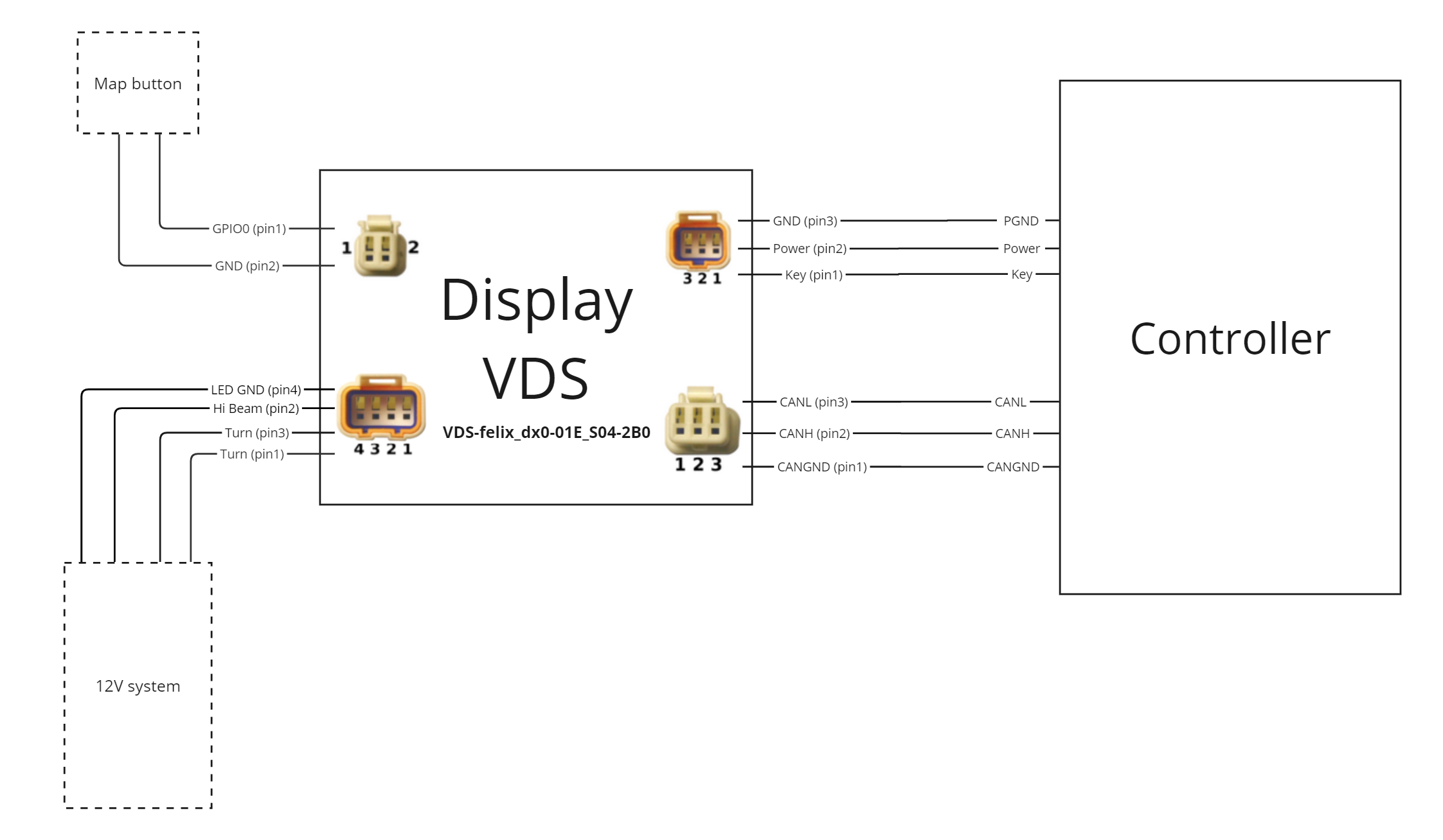
This section provides a typical wiring diagram. The integrator can modify the configuration of the diagram according to their needs and requirements. Creating the wiring diagram for the end application is the responsibility of the integrator.

The VDS display is connected to the controller using power cables (Key, Power, and Ground) and communication cables (CANL, CANH, and Ground). This cable configuration is minimal for the operation of the display. There is also the option to connect an external button and 12V signals (left and right turn indicators, high beam indicator, and 12V Ground).