Integration Guidelines
This section describes the process of the controller integration. It covers important integration aspects of the typical components used in the end-application with the motor inverter.
The section is divided into several categories covering particular components:
- Controller
- Motor
- Battery
- Others
Controller
Monitoring functions
siliXcon brushless motor controllers have inbuilt monitoring functions to protect the controller from dangerous situations. It is important to understand these monitored functions for successful controller integration.
Some of the monitored functions cause degradation of the output current, some disable the power stage, and the status of all these monitors is indicated by the status word.
Motor current monitoring
The motor controller monitors the current flowing through phases A and C (accuracy +-5% from the current measuring range), with phase B calculated from these measurements. All three phases are continuously monitored.
The controller employs two levels of motor current limitations:
The first limitation level is adjustable (parameter Ipeak) and sets the current at which the controller switches to Direct Torque Control (DTC) mode. Instantly, the controller attempts to limit the phase current (this loop lasts for 50 microseconds). This state is indicated by „Overcurrent“ flag in the status word.
The controller's current range versions define the second level. If any phase's value exceeds this threshold, the power stage is immediately shut down, accompanied by an error code signalling this state. The reboot of the controller is required.
DC voltage monitoring
The controller measures its DC bus voltage and in case of dangerous conditions, it can degrade or deactivate the power stage to protect itself from severe damage.
The DC voltage level is sorted into several ranges:
- The controller delivers maximal current without limitation if the battery voltage is below the Maximum working voltage and above the Minimum working voltage.
- The output current is proportionally limited if the battery voltage is above the Maximum working voltage and below the Full limitation voltage. This is indicated by the "Overvoltage" status.
- The output current is fully limited if the battery voltage is above the Full limitation voltage and below the Critical error voltage (max). This state is indicated by the "Overvoltage" status. The controller automatically recovers if the voltage falls below the Full limitation voltage.
- The controller falls into critical error if the battery voltage exceeds the Critical error voltage (max). The controller can be permanently damaged in this region and does not recover automatically, it needs to be turned OFF and ON again.
- The output current is proportionally limited if the battery voltage is below the Minimum working voltage and above the Threshold voltage. This is indicated by the "Undervoltage" status.
- The output current is fully limited if the battery voltage is below the Threshold voltage and above the Critical error voltage (min). This state is indicated by the "Undervoltage" status. The controller automatically recovers if the voltage rises above the Threshold voltage.
- The controller falls into critical error if the battery voltage falls below the Critical error voltage (min). The controller does not recover automatically, it needs to be turned OFF and ON again.
Power stage temperature monitoring
The processor monitors and processes signals from two temperature sensors, each playing a crucial role in monitoring and limiting the output current for safe operation.
The first signal is directly read from the microprocessor and corresponds to the temperature of the controller’s heatsink, influencing the safe operation of the power stage. This value is expressed in °C and is vital for maintaining the temperature within safe limits.
The second signal is derived from PTCs located in the power stage. It's a non-linear signal represented by resistance. Each product is empirically set to protect the power stage from damage.
When one of these signals reaches the limitation threshold, the controller gradually limits the output current until it reaches thermal equilibrium. In extreme cases, it may lead to a complete halt of the motor.
The start of the heatsink temperature limit is set at 90°C. Full limitation occurs at 100°C. The restriction of the controller's output due to temperature is indicated by the respective status bit. It's important to note that even if the heatsink temperature is below 90°C, the output current might still be restricted due to power stage overheating.
Motor Position sensor function monitoring
Knowing the correct rotor position is crucial for effective motor control. The controller is programmed to evaluate an invalid status based on specific criteria for each supported sensor type. When the system detects this condition, the power stage is temporarily deactivated until the system returns to normal values. This invalid status is signalled through the "sensor error" flag in the status word.
Analog circuitry function monitoring
The status of the analogue section is continuously monitored as it plays a critical role in the motor control process. If the system gets a reading outside the defined range, the power stage is deactivated until the value returns to a valid operation range. Simultaneously, the "Analog Error" flag is set in the status word to indicate this deviation from the expected range.
System synchronisation monitoring
Several software loops run within the microprocessor, each bearing a different significance level. Efficient motor control requires the execution of various critical loops within precisely defined periods.
If there is a deviation from these established execution cycles, the power stage is deactivated until the conditions for safe operation are restored. This state is indicated by the "Synchronisation Error" flag in the status word.
Motor overspeeding monitoring
Motor overspeed occurs when the motor runs faster than its maximum speed for the given DC voltage. This situation is dangerous for the controller because uncontrolled current may flow from the motor to the battery. The controller cannot prevent this situation (not fully true if flux weakening is activated) and reacts only by activating the status indicator.
Water and dust protection
The device has been designed with safety measures to ensure effective protection against water and dust. Meeting the defined criteria for water and dust resistance depends on installing the mating signal connectors, proper installation of cables, and using the corresponding blanks on unused pins. We strongly recommend adhering to these measures to ensure an optimal level of protection for the device when used in various environments.
Water sensitive equipment - risk of damage to equipment
Cooling requirements
The controller is designed to be mounted on a surface (heat sink) capable of efficiently dissipating heat generated by the power stage. To ensure sufficient heat dissipation, the used heat sink must have a thermal resistance equal to or lower than the value calculated for the given working conditions. Additionally, it is crucial to ensure that the contact area between the heat sink and the controller is sufficiently flat and clean before installation. To achieve optimal thermal parameters, the use of thermal conductivity paste is recommended.
The controller is designed to operate continuously at a heat sink temperature of up to 90 °C. It is essential to ensure that this temperature is not exceeded during operation in the end application under all operating conditions, thereby ensuring compliance with the declared parameters. If the heat sink temperature exceeds 90 °C, there is a gradual limitation of the output current up to the full limitation value at 100 °C. In case the heat sink temperature exceeds 90 °C during operation, it is recommended to improve cooling options, use a controller with a higher current load, or reduce the power parameters of the end application.
Operation at reduced power – risk of damage to equipment and/or malfunction
Exceeding the intended operating temperature leads to a reduction in maximum output power, potentially diminishing the motor controller's lifespan and causing operational malfunctions.
Reversed polarity protection
Bat+ and Bat- power inputs are not protected against reverse polarity. The power input for logic circuits operating with battery voltage is not protected against reverse polarity.
It is the integrator's responsibility to ensure proper protection against reverse polarity.
Orientation
The controller can be positioned in any orientation except the horizontal position with the connector facing downwards.
It is recommended to place the controller to ensure easy access and visibility of signal connectors, power connectors, and status LEDs.
If multiple controllers are used in a single application, it is necessary to provide adequate cooling for all of them.
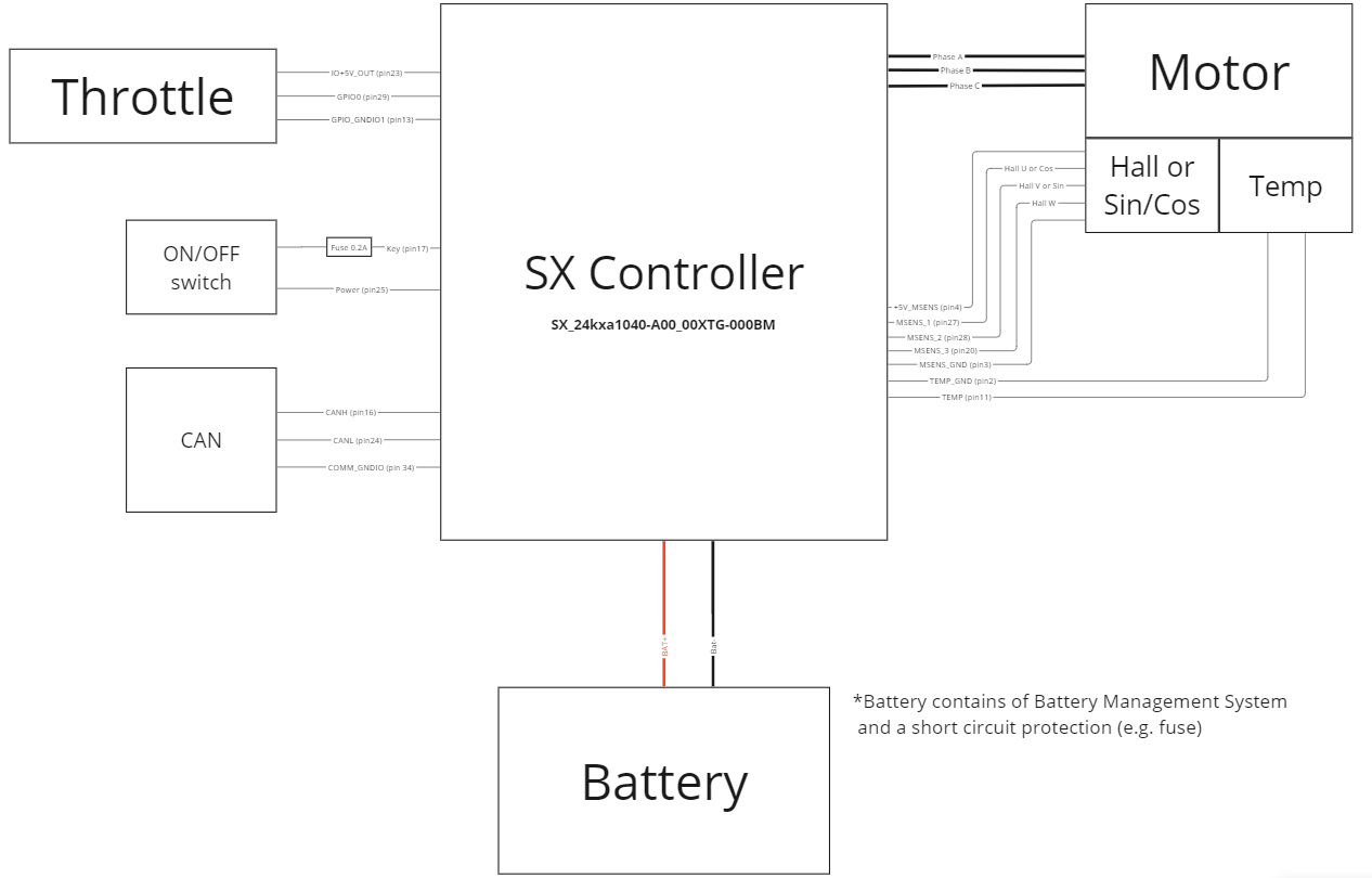
Typical wiring diagram
Incorrect wiring – risk of malfunction/damage to equipment
This section provides a typical wiring diagram. The integrator can modify the configuration of the diagram according to their needs and requirements. Creating the wiring diagram for the end application is the responsibility of the integrator.
Configuring the motor controller for the application
Testing vehicle parameters – risk of personnel injury/damage to equipment
The OEM must thoroughly verify and validate all motor controller settings and functionalities before field use by an end user.
Throughout the parameterization process, it is crucial to exercise proper safety precautions during testing, as incorrect parameter values could compromise the safety-critical functions of the end application.
The OEM bears the responsibility to configure and set up the vehicle in accordance with applicable safety regulations.
Basic controller parametrization can be done with the help of motor identification chapter.
Commissioning the inverter in the prototype of a customer application may require complex parameterization and, if necessary, the development of a special application. For assistance in this case, please contact siliXcon customer support.
The controller supplied for OEM use may already have the final configuration loaded during the manufacturing process. However, it is recommended to perform a complete motor identification after integrating the controller into the end application.
The process of correctly configuring the controller in the end application is the responsibility of the integrator.
Battery
Main DC fuse
Installing a fuse on the main battery lead is recommended to ensure protection in case of a short circuit on the power circuit. The fuse is typically connected between the battery + terminal and the + lead on the controller side.
The selection of a suitable fuse is the integrator's responsibility. It is recommended that the short-circuit fuse ideally blows within approximately 2-3 seconds when the DC current passing through it reaches twice the DC current value for peak power at the specified voltage of the end application.
Main contactor
The contactor can be used in the end application as a component ensuring the disconnection of the power supply from the power stage in the event of a dangerous situation. Under normal conditions, the contactor should not be never open (disconnecting the controller from the DC supply) when the motor is driven.
Disconnecting of DC supply - possible damage to the controller
DC supply should never be disconnected from the controller, if the motor is driven.
The choice of a suitable contactor is the responsibility of the integrator. The control current rating of the contactor should correspond to the maximum anticipated operating current of the end application.
When operating the contactor using a device other than the controller, it is crucial to assess potential implications. Disconnecting the DC power while the system is under load may result in controller damage. In such scenarios, ensuring collaborative coordination between the controller and the device managing the contactor is essential to prevent controller damage.
Motor
Overvoltage from permanent magnet motors
A motor with permanent magnets induces voltage (back-EMF) while spinning. This voltage is directly proportional to the motor's revolutions per minute (rpm). When the motor operates beyond its nominal rpm, it is crucial to ensure that the amplitude of the back EMF remains below the non-operational overvoltage limit.
High voltage – risk of personnel injury and/or damage to equipment
Rotor position and motor temperature sensor
It is recommended to route the motor sensor wires in a single bundle. This bundle should not be routed near the motor or battery power cables. If the end application requires it, cables can be shielded. The shielding conductor should be connected only on the controller side to the ground of the motor sensor.
The motor controller in "a" motor position sensor variant supports two sensors types:
- 3 Hall sensors
- Sin / Cos
The used motor can be equipped with one of these. Detailed technical specifications can be found here
Below are the general characteristics of these two types of sensors.
3 Hall sensors
| Pros | Cons |
|---|---|
| Sense electrical (not mechanical) revolutions. No angle multiplication error occurs – it is suitable for motors with higher number of pole pairs. | Interpolation is needed if used with the VECTOR control algorithm. |
| Low-frequency digital signal – good immunity against electrical interference. | 13% ripple of generated torque during steady operation |
| Ideal for BLDC motors | About 13% to 50% torque ripple during stall or very low-speed operation |
| Cheap |
The signal is usually produced by three Hall sensors placed inside the motor in a 120° (rarely by 60°) span along with one electrical revolution. It can be also emulated by some advanced sensors, such as RLS AM4096. UVW commutation signal is composed of three digital signals. Each signal has two switch points per electrical revolution (the first switch point is from logical HIGH to log. LOW, second is from log. LOW to log. HIGH). Signals are shifted by 120° from each other (variants with signals shifted by 60° also exist). Examples of the signals are shown in the picture below.

When the UVW commutation signal is processed, it gives six discrete levels of rotor position for one electrical revolution. In the six switch points between the levels, the motor position is known with the least ambiguity. This information is enough when the BLDC motor driver algorithm is used. If the VECTOR control algorithm is used, these six switch points are not enough and positions between them have to be extrapolated. UVW commutation signal may not be the ideal choice (especially in applications where a high precision/motion control is required at low RPM) for the VECTOR driver algorithm since position estimation is needed.
Rotor position measurement using the UVW commutation signal is shown in the picture below.

Sin / Cos
| Pros | Cons |
|---|---|
| Absolute and continuous position sensing | Typically sense mechanical revolutions. Angle multiplication error could occur when using a motor with many pole pairs. |
| Suitable for VECTOR driver algorithm | Analog interface – could be sensitive to electrical interference. |
| Suitable for position servo drives | Needs output offset calibration (can be done automatically by the controller) |
Sin-Cos signal is composed of two analogue signals of sinusoidal shape. Signals are phase-shifted by a quarter of the period and one period of sine (or cosine) signal corresponds to one mechanical turn of the motor (see pic. below). This type of signal is usually produced by a sensor consisting of a cylindrical permanent magnet glued to the rotor and a sensor chip located on the stator at a defined distance from the cylindrical magnet.

Motor temperature sensor
The motor controller can measure the temperature of the motor using a temperature sensor. Various types of sensors are supported, they have to meet the following criteria:
- Measured temperature change results in a change of resistance (thermocouples are not supported).
- Resistance of the sensor has to be within a specified range see
Others
Logic supply fuse
It is recommended to install a fuse for the power supply of the logic circuit (KEY pin). The recommended fuse value is 250mA, with fast-acting characteristics. Current loading by external components on this KEY pin should not exceed the fuse rating.
Main switch
The total length of the wires to the main switch should be shorter than 10m.
Throttle
The controller can process a wide range of analogue throttles which provide output signal in the range of 0 - 5 V. It can be a potentiometric, hall type or just an analogue signal provided by a voltage source.
The controller has also a dedicated +5 V power supply for the throttle. Detailed technical specifications can be found in this chapter.
CAN interface
The controller can be a part of the CAN system. CAN interface can be used for commanding the controller or for data exchange between the nodes.
The controller is equipped with an internal 120-ohm CAN terminator resistor. This resistor can be activated by internal configration - check internal HW configuration. Or by the dedicated jumper under the USB plug - check overview.
Detailed technical specifications of the CAN interface can be found in this chapter.
General recommendations for designing signal and power cables
Signal cables
- Keep signal cables separate from power cables.
- When connecting to a PC, use galvanically isolated communication devices to prevent potential damage to the PC.
- Follow the recommended installation of connectors and their pins (according to the manufacturer's recommendations) to ensure reliable operation.
- If possible, avoid using power ground as a signal conductor.
- Consider options for routing signal cables to achieve the best EMC characteristics (emission, immunity to external electromagnetic fields).
Power cables
- The sizing of power cables is contingent upon the application loading profile. siliXcon recommends utilizing silicone insulation (SIFF) cables, taking advantage of their superior thermal rating (higher current capacity) compared to standard cables.
- Ensure that power cables are correctly installed and tightened to prevent overheating or burning of the power terminals/connectors.
- Properly shield all high-voltage cables.
EMC recommendations
- To minimize the risk of electromagnetic interference (EMC), it is advisable to ensure that the motor casing and controller cooler have a high-quality electrical connection (typically achieved through the structural frame). In case the structural frame is not electrically conductive, it is recommended to use a conductor (tinned litz wire) with a sufficient cross-section for electrical connection.
- Battery power cables should be run parallel to each other to minimize the loop area they collectively form.
- Motor power cables should be run parallel to each other to minimize the loop area they collectively form.
- It is recommended to attach motor cables as close as possible to the structural frame (or the cable connecting the controller cooler and the motor casing).
- For CAN communication wires (CANL and CANH), it is recommended to twist them along their entire length.