Integration Guidelines
This section describes the process of the controller integration. It covers important integration aspects of the typical components used in the end application with the motor inverter.
The section is divided into several categories covering phases of integration:
- Before purchase: Covers selection of the appropriate HW and FW of the controller.
- Integration: Describes important integration aspects of the controller.
- Typical wiring diagram: This shows the wiring diagram for the standard version of the controller together with a description of the main components.
- Commissioning: Describes basic steps for controller commissioning.
Before purchase
The motor controller is a configurable device. Defining the HW configuration and selecting the appropriate FW application before purchasing is necessary.
Order lead time depends on the configuration. Variants other than default usually have a longer lead time.
Power features
Below are all possible variants of the controller's power source features. The correct variant must be selected before purchasing, as a hardware modification is necessary.
- e - Precharge
This feature enables automated capacitor precharging via an internal power source with limited current, effectively eliminating excessive inrush current when connecting the battery.
This feature requires the usage of a battery contactor controlled by the motor controller. The battery's positive terminal is connected to the controller's logic (controller turned ON), and the internal power source charges the capacitors with the defined current. Once the capacitors reach the required voltage level, the main battery contactor closes, connecting the battery's positive terminal directly to the controller.
The required precharge voltage level and contactor coil operating voltage can be set by SW parameters according to the particular use case and used components.
Motor sensor variant
The controller supports several motor sensor variants. The correct variant must be specified before purchasing, as a hardware modification may be necessary.
Supported rotor position sensors are:
- Sensorless
- 3 Hall
- Sin-Cos
- Resolver
No additional HW is necessary, the controller simply "computes" rotor position from the measured signals and motor parameters. The sensorless operation does not depend on the motor sensor variant.
BLDC driver algorithm does not require full motor identification for the sensorless operation.
| Pros | Cons |
|---|---|
| Simple and robust - no additional HW required | Relies on motor parameters which can change with the temperature |
| Very precise at higher speeds | Can have problems with operation at zero RPM under load |
| The rotor position calculation loads the main processing unit |
The signal is usually produced by three Hall sensors placed inside the motor in a 120° (rarely by 60°) span along with one electrical revolution. It can be also emulated by some advanced sensors, such as RLS AM4096. UVW commutation signal is composed of three digital signals. Each signal has two switch points per electrical revolution (the first switch point is from logical HIGH to log. LOW, second is from log. LOW to log. HIGH). Signals are shifted by 120° from each other (variants with signals shifted by 60° also exist). Examples of the signals are shown in the picture below.

When the UVW commutation signal is processed, it gives six discrete levels of rotor position for one electrical revolution. In the six switch points between the levels, the motor position is known with the least ambiguity. This information is enough when the BLDC motor driver algorithm is used. If the VECTOR control algorithm is used, these six switch points are not enough and positions between them have to be extrapolated. UVW commutation signal may not be the ideal choice (especially in applications where a high precision/motion control is required at low RPM) for the VECTOR driver algorithm since position estimation is needed.
Rotor position measurement using the UVW commutation signal is shown in the picture below.

Three hall sensors are supported by "a" or "h" motor sensor assembly variant.
| Pros | Cons |
|---|---|
| Sense electrical (not mechanical) revolutions. No angle multiplication error occurs – it is suitable for motors with higher number of pole pairs. | Interpolation is needed if used with the VECTOR control algorithm. |
| Low-frequency digital signal – good immunity against electrical interference. | 13% ripple of generated torque during steady operation |
| Ideal for BLDC motors | About 13% to 50% torque ripple during stall or very low-speed operation |
| Cheap |
Sin-Cos signal is composed of two analogue signals of sinusoidal shape. Signals are phase-shifted by a quarter of the period and one period of sine (or cosine) signal corresponds to one mechanical turn of the motor (see pic. below). This type of signal is usually produced by a sensor consisting of a cylindrical permanent magnet glued to the rotor and a sensor chip located on the stator at a defined distance from the cylindrical magnet.

Sin-Cos motor sensor is supported by "a" motor sensor assembly variant.
BLDC driver algorithm does not support Sin-Cos sensor
| Pros | Cons |
|---|---|
| Absolute and continuous position sensing | Typically sense mechanical revolutions. Angle multiplication error could occur when using a motor with many pole pairs. |
| Suitable for VECTOR driver algorithm | Analog interface – could be sensitive to electrical interference. |
| Suitable for position servo drives | Needs output offset calibration (can be done automatically by the controller) |
Resolver is a motor angle sensor with one excitation winding and two sense (sine and cosine) windings, electrically perpendicular to each other. The resolver is fed by AC voltage of known amplitudes and frequency to the excitation winding. Voltage is measured on both sense windings (sine and cosine winding). The voltage across these sense windings has the same waveform as the voltage across the excitation winding. The amplitude of the sensed voltages is modulated by rotor position, as shown in the figure below. Resolver is a common rotor angle sensor in industry, it is used in high-end drives and servos. Resolvers are usually constructed to sense mechanical revolutions (one period of the modulated sine or cosine voltage corresponds to one mechanical turn). Some resolvers have more pole pairs and can sense electrical revolutions.

Resolver motor sensor is supported by "r" motor sensor assembly variant.
BLDC driver algorithm does not support Resolver sensor
| Pros | Cons |
|---|---|
| Absolute and continuous position sensing | Typically sense mechanical revolutions. Angle multiplication error could occur when using a motor with many pole pairs. |
| Suitable for VECTOR driver algorithm | Analog interface – could be sensitive to electrical interference. |
| Suitable for position servo drives | Higher weight, larger dimensions |
| No offset in sense winding voltage – easy to set up the drive | Higher price |
| Robust solution with no semiconductors or active electronics |
SL controller usually needs to attach a driver for the excitation coil to get a quality signal reading from the resolver.
Voltage and current range
The correct voltage variant must be selected based on the battery voltage working range.
Similarly, the current range must be selected based on the required phase current.
Voltage and current measurement resolution depends on the range. The higher the range is the lower the resolution is.
Powering on method
The device offers several powering methods. The correct variant must be specified before purchasing, as a hardware modification is necessary.
A detailed powering scheme together with its options can be found in the powering circuit's detailed specification.
Driver algorithm selection
The controller can be equipped with two driver algorithms - BLDC and VECTOR. The correct algorithm depends mainly on the used motor and intended use case.
Each of the available algorithms has some advantages and disadvantages:
BLDC
| Pros | Cons |
|---|---|
| Simple | Usually lower efficiency |
| Suitable for applications where precise control is not required | Higher vibrations and noise |
VECTOR
| Pros | Cons |
|---|---|
| Efficient motor control | Requires higher computation power |
| Suitable for all kinds of applications | Driver settings fine-tuning may be required |
FW application
One of the two standard FW applications (LYNX or OPHION) must be selected before the purchase.
Generally, LYNX is more suitable for traction applications, because it has many useful features, settable by parametrization. OPHION on the other hand is simpler and is usually a good choice for general motor control applications.
Integration
Protective functions
The controller has several built-in functions to protect both itself and external components from dangerous states. Understanding these monitored functions is crucial for successful controller integration.
In general, there are three protective mechanisms:
- Controller's diagnostics
- High-priority protective functions
- Low-priority protective functions
Controller's diagnostics
This mechanism aims to avoid damage to the controller. It is divided into two separate functions:
-
Initialization diagnostic: Runs at the start of the controller and checks operating conditions and status of the power stage. The power stage is not activated if there is any problem.
-
Run-time diagnostic: Continuously monitors phase currents and input voltage for dangerous states. If any of these variables overcome the hardcoded thresholds, the powerstage is immediately turned OFF.
In both states the power stage is disabled (MOSFETs are not driven) and the error word indicates the particular issue. The controller also preserves a log of the last error cododes.
High-priority protective functions
This mechanism aims to avoid entering a dangerous state to the controller. The monitored functions cover phase currents, input voltage, temperature, motor position sensor and internal analogue-to-digital converter (ADC).
Some monitored functions (currents, voltages, temperatures) cause a reduction of the output current. Position sensor and ADC error causes temporary disabling of the power stage until the system returns to normal values.
Detailed information can be found in the Driver/Protections chapter. Status of the high-priority limiter is indicated by the status word.
Low-priority protective functions
This mechanism aims to protect external components such as the battery and motor. Monitored functions cause a reduction of the phase current.
More information can be found in the Driver/Limiter chapter. Status of the low-priority limiter is indicated by the limiter word.
Water and dust protection
The device has been designed with safety measures to ensure effective protection against water and dust. Meeting the defined criteria for water and dust resistance depends on installing the mating signal connectors, proper installation of cables, and using the corresponding blanks on unused pins. We strongly recommend adhering to these measures to ensure an optimal level of protection for the device when used in various environments.
Water sensitive equipment - risk of damage to equipment
Cooling requirements
The controller is designed to be mounted on a surface (heat sink) capable of efficiently dissipating heat generated by the power stage. To ensure sufficient heat dissipation, the used heat sink must have a thermal resistance equal to or lower than the value calculated for the given working conditions. Additionally, it is crucial to ensure that the contact area between the heat sink and the controller is sufficiently flat and clean before installation. To achieve optimal thermal parameters, the use of thermal conductivity paste is recommended.
The controller is designed to operate continuously at a heat sink temperature of up to 90 °C. It is essential to ensure that this temperature is not exceeded during operation in the end application under all operating conditions, thereby ensuring compliance with the declared parameters. If the heat sink temperature exceeds 90 °C, there is a gradual limitation of the output current up to the full limitation value at 100 °C. In case the heat sink temperature exceeds 90 °C during operation, it is recommended to improve cooling options, use a controller with a higher current load, or reduce the power parameters of the end application.
Operation at reduced power – risk of damage to equipment and/or malfunction
Exceeding the intended operating temperature leads to a reduction in maximum output power, potentially diminishing the motor controller's lifespan and causing operational malfunctions.
Reversed polarity protection
Bat+ and Bat- power inputs are not protected against reverse polarity. The power input for logic circuits operating with battery voltage is not protected against reverse polarity.
It is the integrator's responsibility to ensure proper protection against reverse polarity.
Orientation
The controller can be positioned in any orientation except the horizontal position with the connector facing downwards.
It is recommended to place the controller to ensure easy access and visibility of signal connectors, power connectors, and status LEDs.
If multiple controllers are used in a single application, it is necessary to provide adequate cooling for all of them.
General recommendations for designing signal and power cables
Signal cables
- Keep signal cables separate from power cables.
- When connecting to a PC, use galvanically isolated communication devices to prevent potential damage to the PC.
- Follow the recommended installation of connectors and their pins (according to the manufacturer's recommendations) to ensure reliable operation.
- If possible, avoid using power ground as a signal conductor.
- Consider options for routing signal cables to achieve the best EMC characteristics (emission, immunity to external electromagnetic fields).
Power cables
- The sizing of power cables is contingent upon the application loading profile. siliXcon recommends utilizing silicone insulation (SIFF) cables, taking advantage of their superior thermal rating (higher current capacity) compared to standard cables.
- Ensure that power cables are correctly installed and tightened to prevent overheating or burning of the power terminals/connectors.
- Properly shield all high-voltage cables.
EMC recommendations
- To minimize the risk of electromagnetic interference (EMC), it is advisable to ensure that the motor casing and controller cooler have a high-quality electrical connection (typically achieved through the structural frame). In case the structural frame is not electrically conductive, it is recommended to use a conductor (tinned litz wire) with a sufficient cross-section for electrical connection.
- Battery power cables should be run parallel to each other to minimize the loop area they collectively form.
- Motor power cables should be run parallel to each other to minimize the loop area they collectively form.
- It is recommended to attach motor cables as close as possible to the structural frame (or the cable connecting the controller cooler and the motor casing).
- For CAN communication wires (CANL and CANH), it is recommended to twist them along their entire length.
Typical wiring diagram
Incorrect wiring – risk of malfunction/damage to equipment
This section provides a typical wiring diagram. The integrator can modify the configuration of the diagram according to their needs and requirements. Creating the wiring diagram for the end application is the responsibility of the integrator.
Below is the typical scheme for the standard variant of the SL controller (48exa1060-400_AFFFG-600BB), together with the description of the main components.
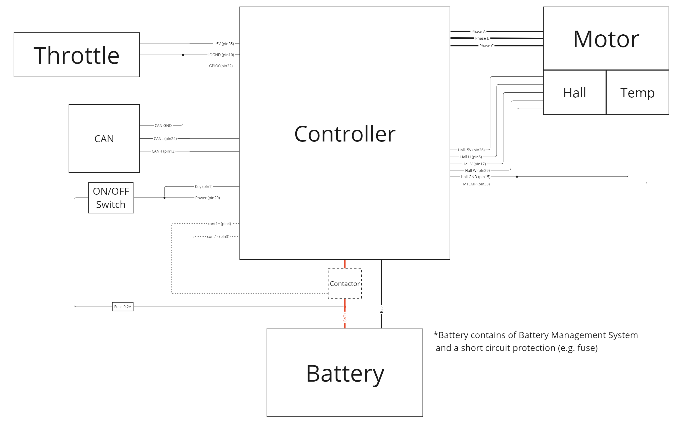
Main DC fuse
Installing a fuse on the main battery lead is recommended to ensure protection in case of a short circuit on the power circuit. The fuse is typically connected between the battery + terminal and the + lead on the controller side.
The selection of a suitable fuse is the integrator's responsibility. It is recommended that the short-circuit fuse ideally blows within approximately 2-3 seconds when the DC current passing through it reaches twice the DC current value for peak power at the specified voltage of the end application.
Main contactor
The contactor can be used in the end application as a component ensuring the disconnection of the power supply from the power stage in the event of a dangerous situation. Under normal conditions, the contactor should not be never open (disconnecting the controller from the DC supply) when the motor is driven.
Disconnecting of DC supply - possible damage to the controller
DC supply should never be disconnected from the controller, if the motor is driven.
The choice of a suitable contactor is the responsibility of the integrator. The control current rating of the contactor should correspond to the maximum anticipated operating current of the end application.
When operating the contactor using a device other than the controller, it is crucial to assess potential implications. Disconnecting the DC power while the system is under load may result in controller damage. In such scenarios, ensuring collaborative coordination between the controller and the device managing the contactor is essential to prevent controller damage.
Logic supply fuse
It is recommended to install a fuse for the power supply of the logic circuit (KEY pin). The recommended fuse value is 250mA, with fast-acting characteristics. Current loading by external components on this KEY pin should not exceed the fuse rating.
Main switch
The controller's logic circuit is powered through the KEY pin. In this case, the KEY pin is connected to the battery + through the external fuse.
The controller is turned ON once the main switch is turned to the "Closed" position and turned OFF if turned to the "Open" position. This is usually done by a SPDT switch.
The total length of the wires to the main switch should be shorter than 10m.
Motor
A motor with permanent magnets induces voltage (back-EMF) while spinning. This voltage is directly proportional to the motor's revolutions per minute (rpm). When the motor operates beyond its nominal rpm, it is crucial to ensure that the amplitude of the back EMF remains below the non-operational overvoltage limit.
High voltage – risk of personnel injury and/or damage to equipment
In this particular case, the motor is equipped with 3 hall sensors together with the motor winding temperature sensor. The used controller is in the motor sensor variant - 'a'. More technical details can be found in Motor position sensor and Motor temperature sensor chapters.
Throttle
The controller can process a wide range of analogue throttles which provide output signal in the range of 0 - 5 V. It can be a potentiometric, hall type or just an analogue signal provided by a voltage source.
The controller has also a dedicated +5 V power supply for the throttle. Detailed technical specifications can be found in this chapter.
CAN interface
The controller can be a part of the CAN system. CAN interface can be used for commanding the controller or for data exchange between the nodes.
Detailed technical specifications of the CAN interface can be found in this chapter.
Configuring the motor controller for the application
Testing vehicle parameters – risk of personnel injury/damage to equipment
The OEM must thoroughly verify and validate all motor controller settings and functionalities before field use by an end user.
Throughout the parameterization process, it is crucial to exercise proper safety precautions during testing, as incorrect parameter values could compromise the safety-critical functions of the end application.
The OEM bears the responsibility to configure and set up the vehicle in accordance with applicable safety regulations.
Basic controller parametrization can be done with the help of motor identification chapter.
Commissioning the inverter in the prototype of a customer application may require complex parameterization and, if necessary, the development of a special application. For assistance in this case, please contact siliXcon customer support.
The controller supplied for OEM use may already have the final configuration loaded during the manufacturing process. However, it is recommended to perform a complete motor identification after integrating the controller into the end application.
The process of correctly configuring the controller in the end application is the responsibility of the integrator.